ELECTRONIC SHIFT LEVER SYSTEM > SYSTEM DESCRIPTION |
| SYSTEM DESCRIPTION |
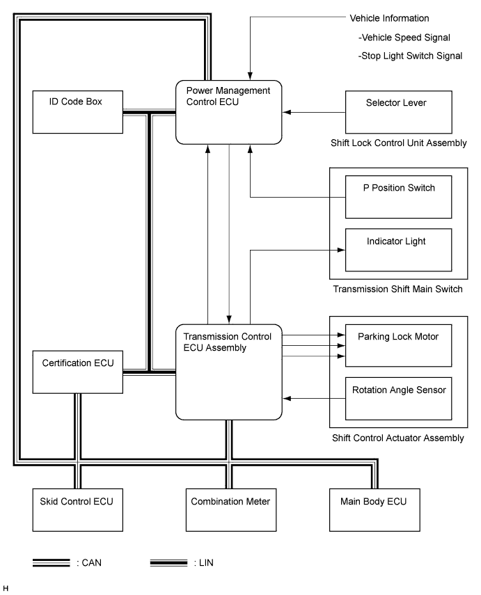
| SYSTEM DIAGRAM |
| Transmitting ECU (Transmitter) | Receiving ECU | Signal | Communication Method |
| Main Body ECU | Power Management Control ECU | Parking brake switch signal | CAN |
| Power Management Control ECU | Power Management Control ECU | Power off preparation signal | CAN |
| Main Body ECU | Transmission control ECU assembly |
| CAN |
| Transmission control ECU assembly | Power Management Control ECU |
| CAN, SIL |
| Power Management Control ECU | Power Management Control ECU |
| CAN |
| Transmission control ECU assembly | Combination Meter | Transmission control ECU assembly trouble signal | CAN |
| Power Management Control ECU | Certification ECU | P position state signal | LIN |
| FUNCTION OF EACH COMPONENT |
| Part Name | Function |
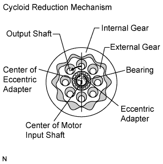
| Shift Control Actuator |
|
| Transmission control ECU assembly |
|
| Parking Lock Mechanism | The parking lock pawl rotates according to the movement of the parking lock rod when the parking lock motor rotates, and engages with the parking gear on the transaxle side, causing the parking lock mechanism to lock or unlock. |
| Power Management Control ECU |
|
| P Position Switch Indicator Light | The P position switch indicator light comes on/goes off to indicate the P lock/unlock status and blinks to indicate a malfunction in the electronic shift lever system. |
| Combination Meter | A malfunction in the transmission control ECU assembly is indicated by the illumination of the master warning light on the combination meter. |
| OPERATION DESCRIPTION |
Operation to switch to the P position:
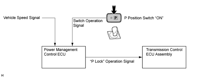
When the park (P) is selected to activate parking lock, a signal is sent to the power management control ECU.
The power management control ECU determines whether "P lock" is possible or not based on this signal and other vehicle information.
If the power management control ECU determines that "P lock" is possible, it sends a "P lock" operation demand signal to the transmission control ECU assembly.
After receiving the signal, the transmission control ECU assembly activates the shift control actuator in order to lock the parking lock mechanism.
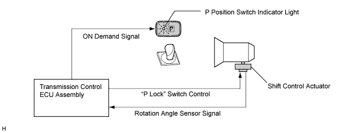
The transmission control ECU assembly controls motor rotation angle based on signals from the rotation angle sensor in the shift control actuator.
 |
Turn on the P position switch indicator light.
Operation to switch to a non-P position:
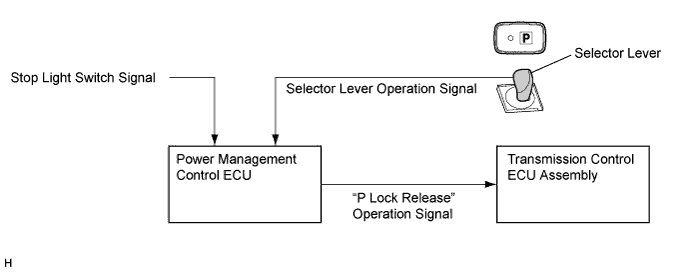
When the hybrid system is started (the vehicle is ready to be driven) and the selector lever is moved to R, N, or D with the brake pedal depressed, a signal is sent to the power management control ECU.
This signal is then sent from the power management control ECU to the transmission control ECU assembly as a "P lock release" operation demand signal.
After receiving the signal, the transmission control ECU assembly activates the shift control actuator in order to unlock the parking lock mechanism.
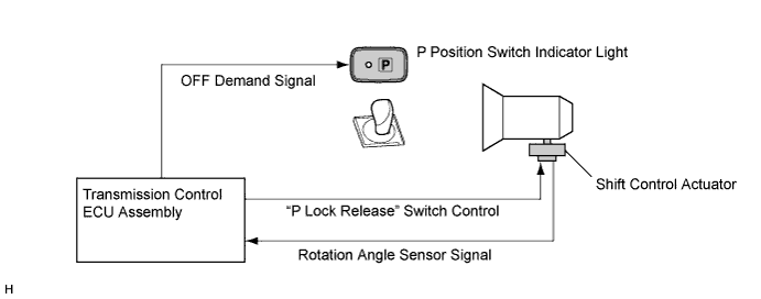
The transmission control ECU assembly controls motor rotation angle based on signals from the rotation angle sensor in the shift control actuator.
Turn off the P position switch indicator light.
| SHIFT POSITION CHANGE FUNCTION |
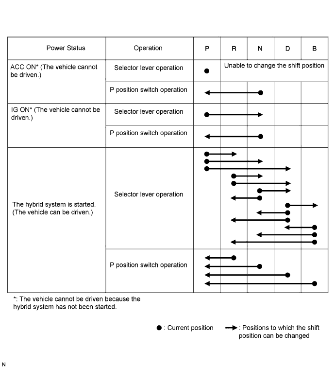
The electronic shift lever system comprehensively determines vehicle conditions and changes the shift position, as shown in the following chart, by cooperating with the shift control function of the hybrid system (except when the reject function, described later, is in operation).
Other than indicated in the following chart, when the power switch is turned off with the vehicle stopped, the shift position is automatically changed to the P position and all power is turned off.
| REJECT FUNCTION |
In the electronic shift lever system, there may be a situation in which a shift change cannot be done for safety reasons. When attempting to move the selector lever in such a situation, the system sounds a reject buzzer inside the meter and changes the shift position as shown in the following table.
| Shift operation which causes reject function to operate | Shift position after rejection |
| Moving the selector lever to any position with park (P) selected and the brake pedal not depressed | Held in the P position |
| Pushing the P position switch while driving | Changed to the N position |
| Moving the selector lever from D to R or R to D while driving at 12 km/h or more | Changed to the N position |
| Moving the selector lever to B from a position other than D or P | Changed to the N position |
| Moving the selector lever to B with park (P) selected and the brake pedal depressed | Held in the P position |
| P POSITION SWITCH INDICATOR LIGHT CONTROL |
The indicator light comes on when the P position switch is pressed (the P position is engaged), goes off when the switch is released (the P position is disengaged) and blinks when the system malfunction occurs.
| DTC No. | Indicator Light | Suspected Cause |
| C2300 | Blinks |
|
| C2301 | Blinks | Shift changing time malfunction |
| C2303 | Normal (Comes on when the P position is engaged and goes off when it is disengaged) | Integration relay lockup |
| C2304 | Blinks | Open or short in shift control actuator assembly [parking lock motor (MUA)] signal circuit |
| C2305 | Blinks | Open or short in shift control actuator assembly [parking lock motor (MVA)] signal circuit |
| C2306 | Blinks | Open or short in shift control actuator assembly [parking lock motor (MWA)] signal circuit |
| C2307 | Blinks | Power source circuit malfunction |
| C2308 | Normal (Comes on when the P position is engaged, and goes off when it is disengaged) | Transmission control ECU assembly internal error |
| C2309 | Blinks | Open in +B signal circuit |
| C2310 | Normal (Comes on when the P position is engaged, and goes off when it is disengaged) | Open or short in BATT signal circuit |
| C2311 | Blinks |
|
| C2315 | Normal (Comes on when the P position is engaged, and goes off when it is disengaged) |
|
| U0146 | Normal (Comes on when the P position is engaged, and goes off when it is disengaged) | CAN communication system malfunction |