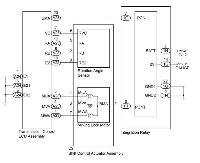
DTC C2300 Actuator System Malfunction |
| DTC No. | DTC Detection Condition | Trouble Area |
| C2300 | Open or short in the integration relay or shift control actuator assembly (parking lock motor or rotation angle sensor), or internal malfunction of the shift control actuator assembly (parking lock motor or rotation angle sensor). |
|
| 1.CHECK FREEZE FRAME DATA |
Connect the intelligent tester to the DLC3.
Turn the power switch on (IG).
Enter the following menus: Chassis / Transmission Control / Trouble Codes.
Read the freeze frame data "Current flag record" of C2300.
| Result | Proceed to |
| OFF | A |
| ON | B |
Turn the power switch off.
|
| ||||
| A | |
 |
| 2.CHECK DTC OUTPUT (TRANSMISSION CONTROL) |
Connect the intelligent tester to the DLC3.
Turn the power switch on (IG).
Enter the following menus: Chassis / Transmission Control / Trouble Codes.
Check if DTCs are output.
| Result | Proceed to |
| Any of the following DTCs are not output. | A |
| Any of the following DTCs are output. | B |
| DTC No. | Relevant Diagnosis |
| C2304 | Open or Short Circuit in U Phase |
| C2305 | Open or Short Circuit in V Phase |
| C2306 | Open or Short Circuit in W Phase |
Turn the power switch off.
|
| ||||
| A | |
|
| 3.CHECK FREEZE FRAME DATA |
Connect the intelligent tester to the DLC3.
Turn the power switch on (IG).
Enter the following menus: Chassis / Transmission Control / Trouble Codes.
Read the freeze frame data of C2300.
| Result | Proceed to |
| IG (+B) voltage is 9 V or more | A |
| IG (+B) voltage is less than 9 V | B |
Turn the power switch off.
|
| ||||
| A | |
|
| 4.CLEAR DTC |
Turn the power switch on (IG).
Enter the following menus: Chassis / Transmission Control / Trouble Codes.
Read and record the DTCs and freeze frame data.
Turn the power switch off.
Disconnect the P CON MAIN fuse and wait for at least 60 seconds.
Check for DTCs again to see if the DTCs are cleared.
| NEXT | |
|
| 5.CHARGE AUXILIARY BATTERY |
Charge the auxiliary battery.
| NEXT | |
|
| 6.CHECK DTC OUTPUT (SIMULATION TEST) |
Connect the intelligent tester to the DLC3.
Release the brake pedal and turn the power switch on (IG).
Depress the brake pedal and move the selector lever to N.
Enter the following menus: Chassis / Transmission Control / Trouble Codes.
Check if DTCs are output.
| Result | Proceed to |
| C2300 is output | A |
| DTC is not output. | B |
Turn the power switch off.
|
| ||||
| A | |
|
| 7.CHECK HARNESS AND CONNECTOR (TRANSMISSION CONTROL ECU ASSEMBLY - SHIFT CONTROL ACTUATOR) |
Disconnect the A23 transmission control ECU assembly connector.
Disconnect the D2 shift control actuator assembly connector.
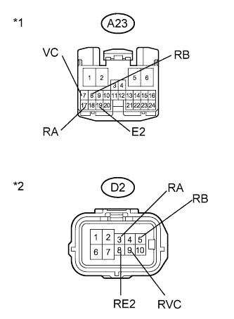 |
Measure the resistance according to the value(s) in the table below.
| Tester Connection | Switch Condition | Specified Condition |
| A23-7 (VC) - D2-9 (RVC) | Power switch off | Below 1 Ω |
| A23-17 (RA) - D2-3 (RA) | Power switch off | Below 1 Ω |
| A23-8 (RB) - D2-5 (RB) | Power switch off | Below 1 Ω |
| A23-19 (E2) - D2-8 (RE2) | Power switch off | Below 1 Ω |
| Tester Connection | Switch Condition | Specified Condition |
| A23-7 (VC) or D2-9 (RVC) - Body ground and other terminals | Power switch off | 10 kΩ or higher |
| A23-17 (RA) or D2-3 (RA) - Body ground and other terminals | Power switch off | 10 kΩ or higher |
| A23-8 (RB) or D2-5 (RB) - Body ground and other terminals | Power switch off | 10 kΩ or higher |
| A23-19 (E2) or D2-8 (RE2) - Body ground and other terminals | Power switch off | 10 kΩ or higher |
| *1 | Front view of wire harness connector (to Transmission Control ECU Assembly) |
| *2 | Front view of wire harness connector (to Shift Control Actuator Assembly) |
Connect the shift control actuator assembly connector.
Connect the transmission control ECU assembly connector.
|
| ||||
| OK | |
|
| 8.CHECK SHIFT CONTROL ACTUATOR ASSEMBLY (ROTATION ANGLE SENSOR) |
Disconnect the A23 transmission control ECU assembly connector.
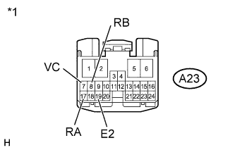 |
Measure the resistance according to the value(s) in the table below.
| Tester Connection | Condition | Specified Condition |
| A23-7 (VC) - A23-17 (RA) | Power switch off | 10 kΩ or higher |
| A23-7 (VC) - A23-8 (RB) | Power switch off | 10 kΩ or higher |
| A23-7 (VC) - A23-19 (E2) | Power switch off | 520 to 600 Ω |
| A23-17 (RA) - A23-8 (RB) | Power switch off | 10 kΩ or higher |
| A23-17 (RA) - A23-19 (E2) | Power switch off | 10 kΩ or higher |
| A23-8 (RB) - A23-19 (E2) | Power switch off | 10 kΩ or higher |
| *1 | Front view of wire harness connector (to Transmission Control ECU Assembly) |
Connect the transmission control ECU assembly connector.
|
| ||||
| OK | |
|
| 9.CHECK HARNESS AND CONNECTOR (TRANSMISSION CONTROL ECU ASSEMBLY - BODY GROUND) |
Disconnect the A24 transmission control ECU assembly connector.
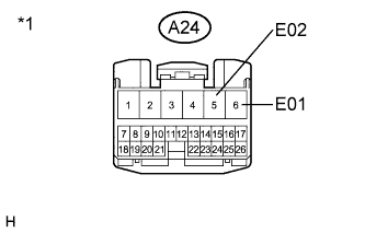 |
Measure the resistance according to the value(s) in the table below.
| Tester Connection | Switch Condition | Specified Condition |
| A24-6 (E01) - Body ground | Power switch off | Below 1 Ω |
| A24-5 (E02) - Body ground | Power switch off | Below 1 Ω |
| *1 | Front view of wire harness connector (to Transmission Control ECU Assembly) |
Connect the transmission control ECU assembly connector.
|
| ||||
| OK | |
|
| 10.CHECK SHIFT CONTROL ACTUATOR ASSEMBLY |
Disconnect the shift control actuator assembly connector.
Remove the shift control actuator 3 bolts (Click here).
Slightly pull the shift control actuator assembly from the hybrid vehicle transaxle.
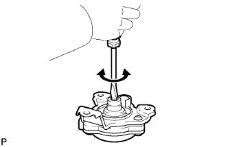 |
Using a screwdriver with its tip wrapped with protective tape or a piece of cloth, rotate the shaft.
|
| ||||
| OK | |
|
| 11.CHECK HYBRID VEHICLE TRANSAXLE ASSEMBLY |
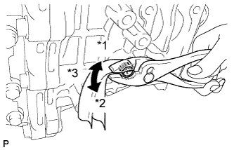 |
Wrap the shaft with a piece of cloth and turn it using pliers.
| *1 | Lock |
| *2 | Unlock |
| *3 | Rotate approximately 20°. |
Set the shaft in the lock position after the inspection.
|
| ||||
| OK | ||
 | ||
| ||
