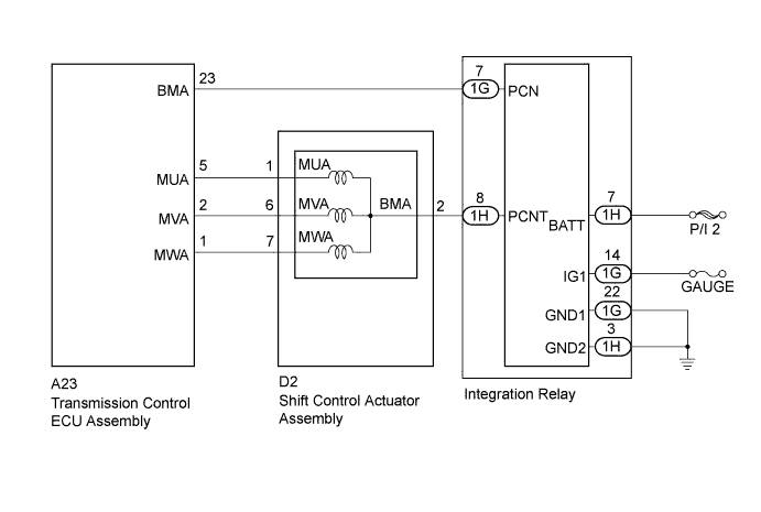
DTC C2303 Short in Power Source Relay Circuit |
| DTC No. | DTC Detection Condition | Trouble Area |
| C2303 | When the integration relay is off, voltage of transmission control ECU terminal MUA, MVA and MWA are 6 V or more for 0.064 seconds or more. |
|
| 1.CHECK SHIFT CONTROL ACTUATOR ASSEMBLY (SHIFT CONTROL ACTUATOR ASSEMBLY POWER SOURCE CIRCUIT) |
Disconnect the D2 shift control actuator assembly connector.
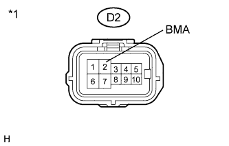 |
Measure the voltage according to the value(s) in the table below.
| Tester Connection | Switch Condition | Specified Condition |
| D2-2 (BMA) - Body ground | Power switch off | Below 1 V |
| *1 | Front view of wire harness connector (to Shift Control Actuator Assembly) |
Connect the shift control actuator assembly connector.
|
| ||||
| OK | |
 |
| 2.CHECK HARNESS AND CONNECTOR (TRANSMISSION CONTROL ECU ASSEMBLY - SHIFT CONTROL ACTUATOR) |
Disconnect the A23 transmission control ECU assembly connector.
Disconnect the D2 shift control actuator assembly connector.
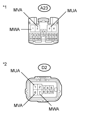 |
Measure the resistance according to the value(s) in the table below.
| Tester Connection | Switch Condition | Specified Condition |
| A23-5 (MUA) or D2-1 (MUA) - Body ground and other terminals | Power switch off | 10 kΩ or higher |
| A23-2 (MVA) or D2-6 (MVA) - Body ground and other terminals | Power switch off | 10 kΩ or higher |
| A23-1 (MWA) or D2-7 (MWA) - Body ground and other terminals | Power switch off | 10 kΩ or higher |
| *1 | Front view of wire harness connector (to Transmission Control ECU Assembly) |
| *2 | Front view of wire harness connector (to Shift Control Actuator Assembly) |
Connect the shift control actuator assembly connector.
Connect the transmission control ECU assembly connector.
|
| ||||
| OK | ||
 | ||
| ||
| 3.CHECK HARNESS AND CONNECTOR (TRANSMISSION CONTROL ECU ASSEMBLY - INTEGRATION RELAY) |
Disconnect the A23 transmission control ECU assembly connector.
Disconnect the 1G integration relay connector.
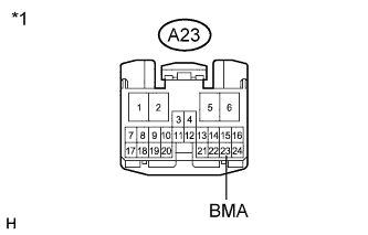 |
Measure the resistance according to the value(s) in the table below.
| Tester Connection | Switch Condition | Specified Condition |
| A23-23 (BMA) - Body ground and other terminals | Power switch off | 10 kΩ or higher |
| *1 | Front view of wire harness connector (to Transmission Control ECU Assembly) |
Connect the integration relay connector.
Connect the transmission control ECU assembly connector.
|
| ||||
| OK | |
|
| 4.CHECK HARNESS AND CONNECTOR (SHIFT CONTROL ACTUATOR ASSEMBLY - INTEGRATION RELAY) |
Disconnect the D2 shift control actuator assembly connector.
Disconnect the 1H integration relay connector.
|
Measure the resistance according to the value(s) in the table below.
| Tester Connection | Switch Condition | Specified Condition |
| D2-2 (BMA) - Body ground and other terminals | Power switch off | 10 kΩ or higher |
| *1 | Front view of wire harness connector (to Shift Control Actuator Assembly) |
Connect the integration relay connector.
Connect the shift control actuator assembly connector.
|
| ||||
| OK | ||
| ||
| ||

