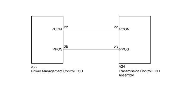
DTC C2315 HV System |
| DTC No. | DTC Detection Condition | Trouble Area |
| C2315 | With the power switch on (IG) (IG circuit malfunction is not detected), a malfunction signal is received from the power management control ECU for 2 second or more. | Power management control ECU |
| 1.CHECK DTC OUTPUT (HV) |
Connect the intelligent tester to the DLC3.
Turn the power switch on (IG).
Enter the following menus: Powertrain / Hybrid Control / Trouble Codes.
Check if DTCs are output.
| Result | Proceed to |
| Any of the following DTCs are not output. | A |
| Any of the following DTCs are output. | B |
| DTC No. | Relevant Diagnosis |
| P0851-579 | Park/Neutral Switch Input Circuit Low |
| P0852-580 | Park/Neutral Switch Input Circuit High |
| P085D-599 | Gear Shift Control Module "A" Performance |
| P0861-597 | Gear Shift Control Module "A" Communication Circuit Low |
| P0862-598 | Gear Shift Control Module "A" Communication Circuit High |
| U1107-436 | Lost Communication with Power Management Module |
Turn the power switch off.
|
| ||||
| A | |
 |
| 2.CLEAR DTC |
Connect the intelligent tester to the DLC3.
Turn the power switch on (IG).
Enter the following menus: Chassis / Transmission Control / Trouble Codes.
Read and record the DTCs and freeze frame data.
Clear DTCs and freeze frame data.
Turn the power switch off.
| NEXT | |
|
| 3.CHECK DTC OUTPUT (ALL) |
Connect the intelligent tester to the DLC3.
Turn the power switch on (IG).
Wait for 2 seconds or more.
Check for DTCs of all systems by following the prompts on the intelligent tester screen.
Check if DTCs are output.
| Result | Proceed to |
| DTC is not output. | A |
| C2315 only is output. | B |
| C2315 and other DTCs are output together. | C |
Turn the power switch off.
|
| ||||
|
| ||||
| A | ||
 | ||
| ||
