 |
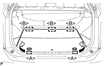
Disengage the 2 guides <A> as shown in the illustration.
POWER SWITCH > REMOVAL |
| 1. PRECAUTION (w/ Navigation System for HDD) |
| 2. REMOVE REAR NO. 2 FLOOR BOARD |
|
Disengage the 2 guides <A> as shown in the illustration.
Disengage the 3 guides <B> and remove the rear No. 2 floor board.
| 3. REMOVE REAR DECK FLOOR BOX |
Remove the rear deck floor box.
| 4. REMOVE REAR NO. 3 FLOOR BOARD |
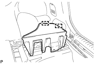 |
Disengage the 2 guides and remove the rear No. 3 floor board.
| 5. DISCONNECT CABLE FROM NEGATIVE BATTERY TERMINAL |
| 6. REMOVE INTEGRATION CONTROL AND PANEL ASSEMBLY |
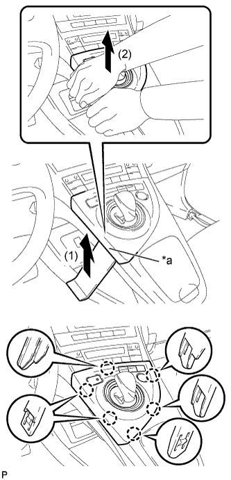 |
Using a moulding remover, slightly lift the panel at the position shown in the illustration.
| *a | Lift slightly |
Pull the integration control and panel assembly in the direction indicated by the arrow to disengage the 6 claws.
Disconnect each connector and remove the integration control and panel assembly.
| 7. REMOVE LOWER CENTER INSTRUMENT CLUSTER FINISH PANEL SUB-ASSEMBLY |
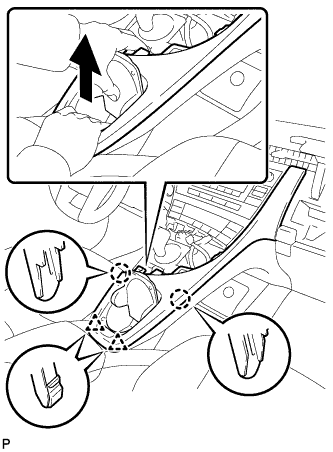 |
Pull the lower center instrument cluster finish panel sub-assembly in the direction indicated by the arrow to disengage the 2 claws and 2 clips.
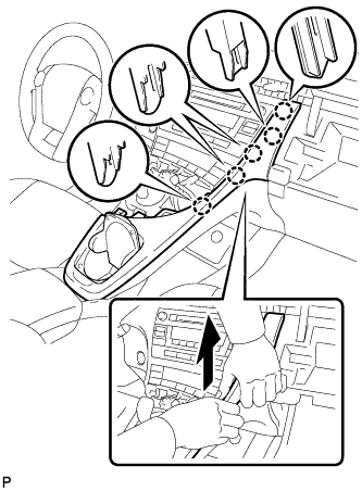 |
Pull the lower center instrument cluster finish panel sub-assembly in the direction indicated by the arrow to disengage the 5 claws and remove the lower center instrument cluster finish panel sub-assembly.
| 8. REMOVE INSTRUMENT CLUSTER FINISH PANEL GARNISH |
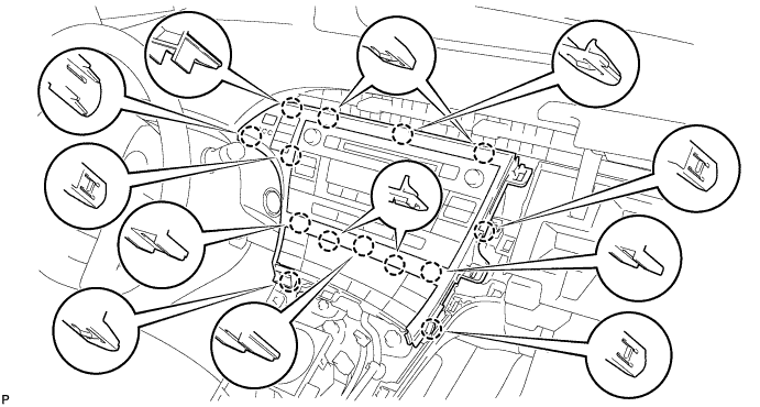
Disengage the 14 claws.
Disconnect the connector and remove the instrument cluster finish panel garnish.
| 9. REMOVE UPPER INSTRUMENT PANEL FINISH PANEL SUB-ASSEMBLY |
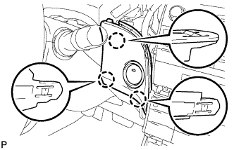 |
Disengage the 3 claws.
Disconnect the connector and remove the upper instrument panel finish panel sub-assembly.
| 10. REMOVE POWER SWITCH |
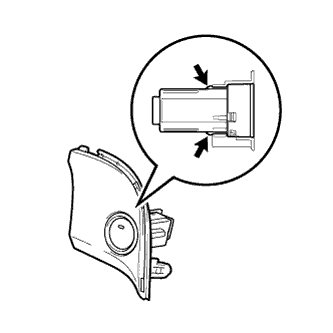 |
Detach the 2 claws and remove the power switch.