| NG |  |
| REPAIR OR REPLACE HARNESS OR CONNECTOR (AUXILIARY BATTERY - POWER MANAGEMENT CONTROL ECU) |
ENTRY AND START SYSTEM (for Start Function) > Power Source Mode does not Change to ON (IG) |
| 1.CHECK HARNESS AND CONNECTOR (AUXILIARY BATTERY - POWER MANAGEMENT CONTROL ECU) |
Disconnect the L5 and L6 connectors from the power management control ECU.
Measure the voltage according to the value(s) in the table below.
| Tester Connection | Condition | Specified Condition |
| L5-1 (AM22) - Body ground | Always | 9.5 to 16 V |
| L6-7 (AM21) - Body ground | Always | 9.5 to 16 V |
|
| ||||
| OK | |
 |
| 2.CHECK HARNESS AND CONNECTOR (POWER MANAGEMENT CONTROL ECU - BODY GROUND) |
Measure the resistance according to the value(s) in the table below.
| Tester Connection | Condition | Specified Condition |
| L5-5 (E01) - Body ground | Always | Below 1 Ω |
| L5-6 (E1) - Body ground | Always | Below 1 Ω |
| L6-4 (E12) - Body ground | Always | Below 1 Ω |
| L6-5 (E02) - Body ground | Always | Below 1 Ω |
|
| ||||
| OK | |
|
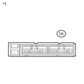
| 3.INSPECT IG2 RELAY |
 |
Remove the engine room relay block assembly.
Measure the resistance according to the value(s) in the table below.
| Tester Connection | Condition | Specified Condition |
| 1A-2 - 1A-3 | 20°C (68°F) | 130 to 230 Ω |
| *1 | Component without harness connected (Engine Room Relay Block) |
|
| ||||
| OK | |
|
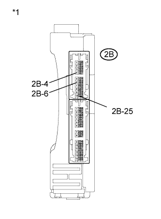
| 4.INSPECT INSTRUMENT PANEL JUNCTION BLOCK ASSEMBLY (IG1 NO. 1, IG1 NO. 2 AND IG1 NO. 3 RELAY) |
 |
Remove the instrument panel junction block assembly.
Measure the resistance according to the value(s) in the table below.
| Tester Connection | Condition | Specified Condition |
| 2B-25 - 2B-4 | 20°C (68°F) | 52.32 to 79.32 Ω |
| 2B-25 - 2B-6 | 20°C (68°F) | 52.32 to 79.32 Ω |
| 2B-4 - 2B-6 | Always | Below 1 Ω |
| *1 | Component without harness connected (Instrument Panel Junction Block Assembly) |
|
| ||||
| OK | |
|
| 5.CHECK HARNESS AND CONNECTOR (POWER MANAGEMENT CONTROL ECU - INSTRUMENT PANEL J/B) |
Measure the resistance according to the value(s) in the table below.
| Tester Connection | Condition | Specified Condition |
| L6-2 (IG1D) - 2B-25 | Always | Below 1 Ω |
| L6-2 (IG1D) - Body ground | Always | 10 kΩ or higher |
|
| ||||
| OK | |
|
| 6.CHECK HARNESS AND CONNECTOR (INSTRUMENT PANEL JUNCTION BLOCK ASSEMBLY - BODY GROUND) |
Measure the resistance according to the value(s) in the table below.
| Tester Connection | Condition | Specified Condition |
| 2B-4 - Body ground | Always | Below 1 Ω |
| 2B-6 - Body ground | Always | Below 1 Ω |
|
| ||||
| OK | |
|
| 7.CHECK HARNESS AND CONNECTOR (POWER MANAGEMENT CONTROL ECU - IG2 RELAY) |
Measure the resistance according to the value(s) in the table below.
| Tester Connection | Condition | Specified Condition |
| A22-2 (IG2D) - 1A-2 | Always | Below 1 Ω |
| A22-2 (IG2D) - Body ground | Always | 10 kΩ or higher |
|
| ||||
| OK | |
|
| 8.CHECK HARNESS AND CONNECTOR (ENGINE ROOM RELAY BLOCK ASSEMBLY - BODY GROUND) |
Measure the resistance according to the value(s) in the table below.
| Tester Connection | Condition | Specified Condition |
| 1A-3 - Body ground | Always | Below 1 Ω |
|
| ||||
| OK | |
|
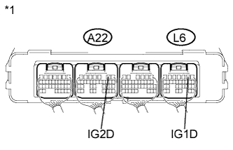
| 9.CHECK POWER MANAGEMENT CONTROL ECU |
 |
Install the instrument panel junction block assembly.
Install the engine room relay block.
Reconnect the A22 and L6 connectors.
Measure the voltage according to the value(s) in the table below.
| Tester Connection | Condition | Specified Condition |
| A22-2 (IG2D) - Body ground | Power switch on (IG) | Output voltage at terminal AM21 or AM22 is -2.5 V or more |
| L6-2 (IG1D) - Body ground | Power switch on (IG) | Output voltage at terminal AM21 or AM22 is -2.5 V or more |
| *1 | Component with harness connected (Power Management Control ECU) |
|
| ||||
| OK | ||
 | ||
| ||