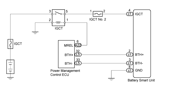
DTC P0AFC-123 Hybrid Battery Pack Sensor Module |
| DTC No. | DTC Detection Condition | Trouble Area |
| P0AFC-123 | The power management control ECU receives an error signal from the battery smart unit. |
|
| 1.CHECK HARNESS AND CONNECTOR (IGCT VOLTAGE) |
Disconnect the cable from the negative (-) battery terminal.
Check that the service plug grip is not installed.
Remove the No. 1 hybrid vehicle battery carrier bracket sub-assembly (Click here).
Connect the cable to the negative (-) battery terminal.
Turn the power switch on (IG).
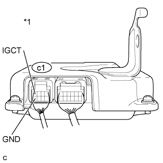 |
Measure the voltage according to the value(s) in the table below.
| Tester Connection | Switch Condition | Specified Condition |
| c1-4 (IGCT) - c1-8 (GND) | Power switch on (IG) | 11 to 14 V |
| *1 | Component with harness connected (Battery Smart Unit) |
Turn the power switch off.
Install the No. 1 hybrid vehicle battery carrier bracket sub-assembly (Click here).
|
| ||||
| OK | ||
 | ||
| ||
| 2.CHECK FUSE (IGCT, IGCT NO. 2) |
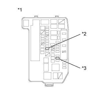 |
Remove the IGCT and IGCT No. 2 fuses from the engine room junction block assembly.
| *1 | Engine Room Junction Block Assembly |
| *2 | IGCT Fuse |
| *3 | IGCT No. 2 Fuse |
Measure the resistance according to the value(s) in the table below.
| Tester Connection | Condition | Specified Condition |
| IGCT fuse | Always | Below 1 Ω |
| IGCT No. 2 fuse | Always | Below 1 Ω |
Install the IGCT and IGCT No. 2 fuses to the engine room junction block assembly.
|
| ||||
| OK | |
 |
| 3.CHECK RELAY (IGCT) |
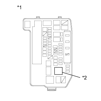 |
Remove the IGCT relay from the engine room junction block assembly.
| *1 | Engine Room Junction Block Assembly |
| *2 | IGCT Relay |
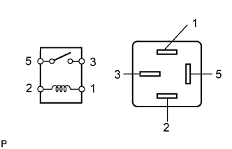 |
Measure the resistance according to the value(s) in the table below.
| Tester Connection | Condition | Specified Condition |
| 3 - 5 | Auxiliary battery voltage is applied between terminals 1 and 2 | 10 kΩ or more |
| Auxiliary battery voltage is not applied between terminals 1 and 2 | below 1 Ω |
Install the IGCT relay to the engine room junction block assembly.
|
| ||||
| OK | |
|
| 4.CHECK HARNESS AND CONNECTOR (IGCT RELAY - BATTERY SMART UNIT) |
Disconnect the cable from the negative (-) battery terminal.
|
Remove the IGCT relay from the engine room junction block assembly.
| *1 | Engine Room Junction Block Assembly |
| *2 | IGCT Relay |
Check that the service plug grip is not installed.
Remove the No. 1 hybrid vehicle battery carrier bracket sub-assembly (Click here).
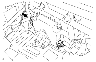 |
Disconnect only the c1 connector of the battery smart unit.
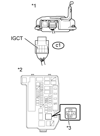 |
Measure the resistance according to the value(s) in the table below.
| Tester Connection | Switch Condition | Specified Condition |
| IGCT relay terminal 5 - c1-4 (IGCT) | Power switch off | Below 1 Ω |
| *1 | Rear view of wire harness connector (to Battery Smart Unit) |
| *2 | Engine Room Junction Block Assembly |
| *3 | IGCT relay terminal 5 |
Connect the c1 connector of the battery smart unit.
Install the No. 1 hybrid vehicle battery carrier bracket sub-assembly (Click here).
Install the IGCT relay to the engine room junction block assembly.
Connect the cable to the negative (-) battery terminal.
|
| ||||
| OK | ||
| ||
| ||

