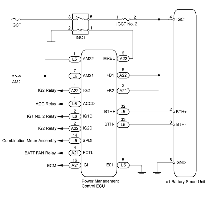
DTC U029A-123 Lost Communication with Hybrid Battery Pack Sensor Module |
| DTC No. | DTC Detection Condition | Trouble Area |
| U029A-123 | Serial communication error between the battery smart unit and the power management control ECU (The power management control ECU did not receive signals from the battery smart unit.) (1 trip detection) |
|
| 1.CHECK DTC OUTPUT (HV) |
Connect the intelligent tester to the DLC3.
Turn the power switch on (IG).
Enter the following menus: Powertrain / Hybrid Control / Trouble Codes.
Read output DTCs (Click here).
| Result | Proceed to |
| Only U029A-123 is output. | A |
| DTCs other than U029A-123 are also output. | B |
Disconnect the intelligent tester from the DLC3.
|
| ||||
| A | |
 |
| 2.CHECK HARNESS AND CONNECTOR (IGCT VOLTAGE) |
Disconnect the cable from the negative (-) battery terminal.
Check that the service plug grip is not installed.
Remove the No. 1 hybrid vehicle battery carrier bracket sub-assembly (Click here).
Connect the cable to the negative (-) battery terminal.
Turn the power switch on (IG).
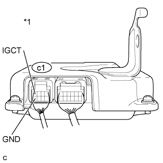 |
Measure the voltage according to the value(s) in the table below.
| Tester Connection | Switch Condition | Specified Condition |
| c1-4 (IGCT) - c1-8 (GND) | Power switch on (IG) | 11 to 14 V |
| *1 | Component with harness connected (Battery Smart Unit) |
Turn the power switch off.
Install the No. 1 hybrid vehicle battery carrier bracket sub-assembly (Click here).
|
| ||||
| OK | |
|
| 3.CHECK HARNESS AND CONNECTOR (POWER MANAGEMENT CONTROL ECU - BATTERY SMART UNIT) |
Disconnect the cable from the negative (-) battery terminal.
Check that the service plug grip is not installed.
Disconnect connector L5 from the power management control ECU (Click here).
Remove the No. 1 hybrid vehicle battery carrier bracket sub-assembly (Click here).
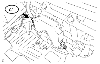 |
Disconnect connector c1 from the battery smart unit.
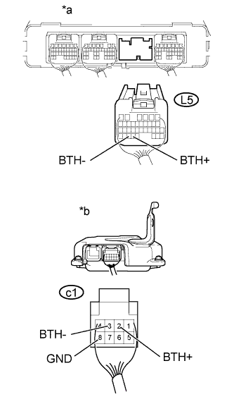 |
Measure the resistance according to the value(s) in the table below.
| Tester Connection | Switch Condition | Specified Condition |
| L5-32 (BTH+) - c1-2 (BTH+) | Power switch off | Below 1 Ω |
| L5-33 (BTH-) - c1-3 (BTH-) | Power switch off | Below 1 Ω |
| c1-2 (BTH+) - c1-8 (GND) and Body ground | Power switch off | 10 kΩ or higher |
| c1-3 (BTH-) - c1-8 (GND) and Body ground | Power switch off | 10 kΩ or higher |
| *a | Rear view of wire harness connector (to Power Management Control ECU) |
| *b | Rear view of wire harness connector (to Battery Smart Unit) |
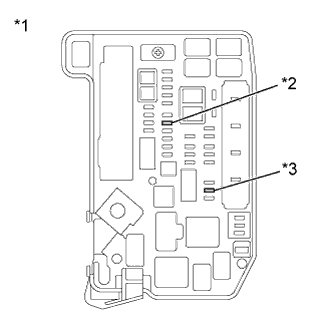 |
Remove the IGCT NO. 2 fuse and AM2 fuse from the engine room junction block assembly.
| *1 | Engine Room Junction Block Assembly |
| *2 | AM2 Fuse |
| *3 | IGCT NO. 2 Fuse |
Disconnect all connectors from the power management control ECU.
Measure the resistance according to the value(s) in the table below.
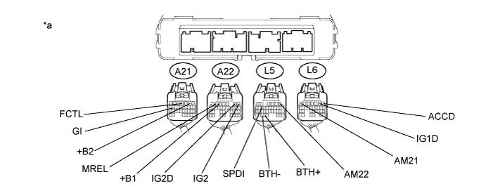
| Tester Connection | Switch Condition | Specified Condition |
| L5-32 (BTH+) - L6-7 (AM21) | Power switch off | 10 kΩ or higher |
| L5-32 (BTH+) - L5-1 (AM22) | Power switch off | 10 kΩ or higher |
| L5-32 (BTH+) - A21-2 (+B2) | Power switch off | 10 kΩ or higher |
| L5-32 (BTH+) - A22-5 (+B1) | Power switch off | 10 kΩ or higher |
| L5-32 (BTH+) - A22-6 (MREL) | Power switch off | 10 kΩ or higher |
| L5-32 (BTH+) - A22-1 (IG2) | Power switch off | 10 kΩ or higher |
| L5-32 (BTH+) - L6-1 (ACCD) | Power switch off | 10 kΩ or higher |
| L5-32 (BTH+) L6-2 (IG1D) | Power switch off | 10 kΩ or higher |
| L5-32 (BTH+) - A22-2 (IG2D) | Power switch off | 10 kΩ or higher |
| L5-32 (BTH+) - A21-4 (FCTL) | Power switch off | 10 kΩ or higher |
| L5-32 (BTH+) - L5-14 (SPDI) | Power switch off | 10 kΩ or higher |
| L5-32 (BTH+) - A21-16 (GI) | Power switch off | 10 kΩ or higher |
| L5-33 (BTH-) - L6-7 (AM21) | Power switch off | 10 kΩ or higher |
| L5-33 (BTH-) - L5-1 (AM22) | Power switch off | 10 kΩ or higher |
| L5-33 (BTH-) - A21-2 (+B2) | Power switch off | 10 kΩ or higher |
| L5-33 (BTH-) - A22-5 (+B1) | Power switch off | 10 kΩ or higher |
| L5-33 (BTH-) - A22-6 (MREL) | Power switch off | 10 kΩ or higher |
| L5-33 (BTH-) - A22-1 (IG2) | Power switch off | 10 kΩ or higher |
| L5-33 (BTH-) - L6-1 (ACCD) | Power switch off | 10 kΩ or higher |
| L5-33 (BTH-) - L6-2 (IG1D) | Power switch off | 10 kΩ or higher |
| L5-33 (BTH-) - A22-2 (IG2D) | Power switch off | 10 kΩ or higher |
| L5-33 (BTH-) - L5-14 (SPDI) | Power switch off | 10 kΩ or higher |
| L5-33 (BTH-) - A21-4 (FCTL) | Power switch off | 10 kΩ or higher |
| L5-33 (BTH-) - A21-16 (GI) | Power switch off | 10 kΩ or higher |
| *a | Rear view of wire harness connector (to Power Management Control ECU) | - | - |
Connect the cable to the negative (-) battery terminal.
Connect the battery smart unit connector.
Install the No. 1 hybrid vehicle battery carrier bracket sub-assembly (Click here).
Connect the power management control ECU connectors (Click here).
|
| ||||
| OK | |
|
| 4.CHECK POWER MANAGEMENT CONTROL ECU |
Check that the service plug grip is not installed.
Remove the No. 1 hybrid vehicle battery carrier bracket sub-assembly (Click here).
|
Disconnect connector c1 from the battery smart unit.
Turn the power switch on (IG).
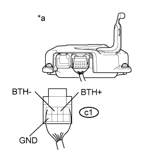 |
Measure the voltage according to the value(s) in the table below.
| Tester Connection | Switch Condition | Specified Condition |
| c1-2 (BTH+) - c1-8 (GND) | Power switch on (IG) | 2.3 to 2.7 V |
| c1-3 (BTH-) - c1-8 (GND) | Power switch on (IG) | 2.3 to 2.7 V |
| *a | Rear view of wire harness connector (to Battery Smart Unit) |
Turn the power switch off.
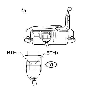 |
Measure the resistance according to the value(s) in the table below.
| Tester Connection | Switch Condition | Specified Condition |
| c1-2 (BTH+) - c1-3 (BTH-) | Power switch off | 4.4 to 5.4 kΩ |
| *a | Rear view of wire harness connector (to Battery Smart Unit) |
Connect the battery smart unit connector.
Install the No. 1 hybrid vehicle battery carrier bracket sub-assembly (Click here).
|
| ||||
| OK | ||
 | ||
| ||
