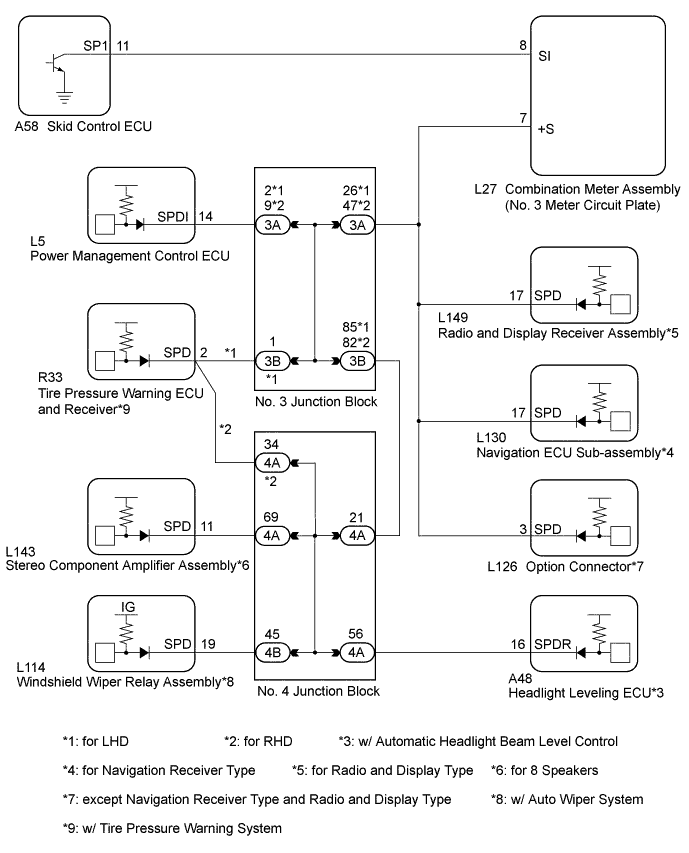
AUDIO AND VISUAL SYSTEM > Vehicle Speed Signal Circuit between Radio Receiver and Combination Meter |
| 1.CHECK VEHICLE SIGNAL (OPERATION CHECK) |
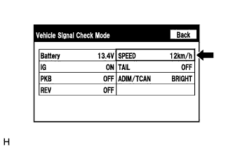 |
Enter the "Vehicle Signal Check Mode" screen. Refer to Check Vehicle Signal Check Mode in Operation Check (Click here).
While driving the vehicle, compare the "SPEED" indicator to the reading on the speedometer. Check if these readings are almost equal.
|
| ||||
| OK | ||
 | ||
| ||
| 2.INSPECT NO. 3 METER CIRCUIT PLATE (OUTPUT WAVEFORM) |
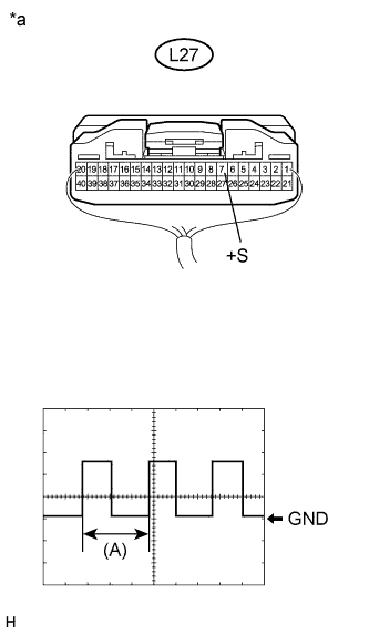 |
Check the output waveform.
Remove the No. 3 meter circuit plate with the connector still connected.
Connect an oscilloscope to terminal L27-7 (+S) and body ground.
Turn the power switch on (IG).
Turn a wheel slowly.
Check the signal waveform according to the condition(s) in the table below.
| Item | Condition |
| Measurement terminal | L27-7 (+S) - Body ground |
| Tool setting | 5 V/DIV., 20 ms./DIV. |
| Vehicle condition | Wheel being rotated |
| *a | Component with harness connected (No. 3 Meter Circuit Plate) |
|
| ||||
| OK | |
 |
| 3.INSPECT RADIO AND DISPLAY RECEIVER ASSEMBLY (INPUT WAVEFORM) |
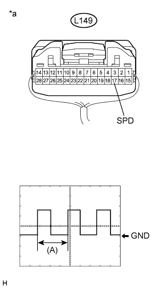 |
Check the input waveform.
Remove the radio and display receiver assembly with the connector still connected.
Connect an oscilloscope to terminal L149-17 (SPD) and body ground.
Turn the power switch on (IG).
Turn a wheel slowly.
Check the signal waveform according to the condition(s) in the table below.
| Item | Condition |
| Measurement terminal | L149-17 (SPD) - Body ground |
| Tool setting | 5 V/DIV., 20 ms./DIV. |
| Vehicle condition | Wheel being rotated |
| *a | Component with harness connected (Radio and Display Receiver Assembly) |
|
| ||||
| OK | ||
| ||
| ||

