REAR SPEED SENSOR > INSTALLATION |
| 1. INSTALL REAR AXLE HUB AND BEARING ASSEMBLY |
Install the rear axle hub and bearing assembly .
| 2. INSPECT REAR AXLE HUB BEARING LOOSENESS |
![]() |
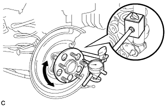
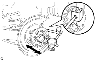
Using a dial indicator, check for looseness near the center of the axle hub.
| 3. INSPECT REAR AXLE HUB RUNOUT |
![]() |
Using a dial indicator, check for runout on the surface of the axle hub outside the rear axle hub bolt.
| 4. INSTALL REAR DISC |
![]() |
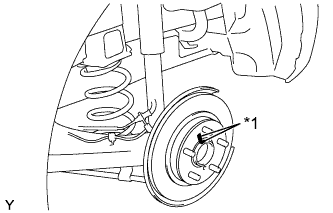
Align the matchmarks of the disc and axle hub, and install the disc.
| *1 | Matchmark |
| 5. INSTALL REAR DISC BRAKE CALIPER ASSEMBLY |
![]() |
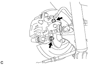
Install the rear disc brake caliper assembly with the 2 bolts.
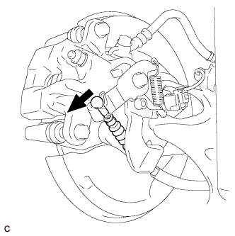
| 6. CONNECT NO. 3 PARKING BRAKE CABLE ASSEMBLY |
![]() |
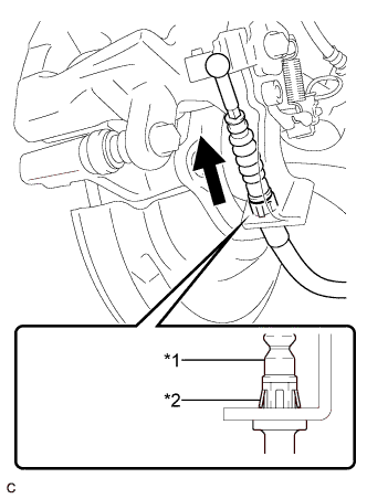
Install the No. 3 parking brake cable assembly to the rear disc brake cylinder assembly.
| *1 | No. 3 Parking Brake Cable Assembly |
| *2 | Clip |
![]() |
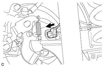
Connect the No. 3 parking brake cable assembly to the rear disc brake cylinder assembly.
| 7. CONNECT REAR SPEED SENSOR WIRE |
![]() |
Connect the rear speed sensor wire connector to the rear speed sensor.
| 8. ADJUST PARKING BRAKE PEDAL TRAVEL (for LHD) |
Remove the lower instrument panel finish panel assembly .
Completely release the parking brake pedal.
![]() |
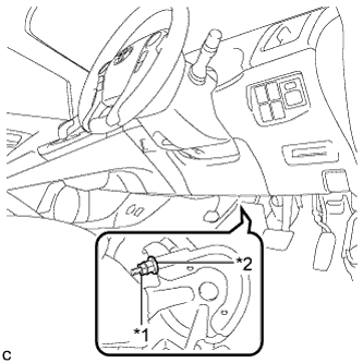
Loosen the lock nut and the adjusting nut to completely release the parking brake cable.
| *1 | Lock Nut |
| *2 | Adjusting Nut |
Turn the adjusting nut until the parking brake pedal travel is corrected to be within the specified range.
![]() |
Using a wrench or an equivalent tool, hold the adjusting nut and tighten the lock nut.
| *1 | Lock Nut |
| *2 | Adjusting Nut |
Operate the parking brake pedal 3 to 4 times, and check the parking brake pedal travel.
Check whether the parking brake drags or not.
Install the lower instrument panel finish panel assembly .
| 9. ADJUST PARKING BRAKE PEDAL TRAVEL (for RHD) |
Remove the No. 2 instrument panel under cover sub-assembly.
Completely release the parking brake pedal.
![]() |
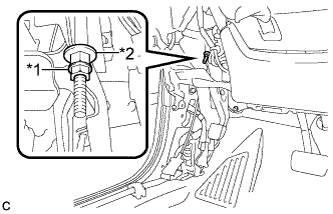
Loosen the lock nut and the adjusting nut to completely release the parking brake cable.
| *1 | Lock Nut |
| *2 | Adjusting Nut |
Turn the adjusting nut until the parking brake pedal travel is corrected to be within the specified range.
![]() |
Using a wrench or an equivalent tool, hold the adjusting nut and tighten the lock nut.
| *1 | Lock Nut |
| *2 | Adjusting Nut |
Operate the parking brake pedal 3 to 4 times, and check the parking brake pedal travel.
Check whether the parking brake drags or not.
Install the No. 2 instrument panel under cover sub-assembly.
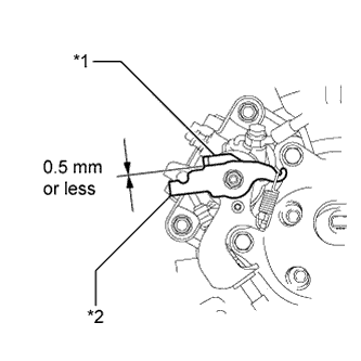
| 10. INSPECT REAR DISC BRAKE CYLINDER OPERATION LEVER AND STOPPER CLEARANCE |
![]() |
Release the parking brake lever and check that the clearance measurement between the rear disc brake cylinder operation lever and the stopper is within the specified range.
| *1 | Stopper |
| *2 | Operation Lever |
| 11. INSTALL LOWER INSTRUMENT PANEL FINISH PANEL ASSEMBLY (for LHD) |
Connect each connector.
Engage the clamp.
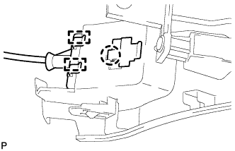
![]() |
Engage the 2 guides and claw to connect the hood lock control cable.
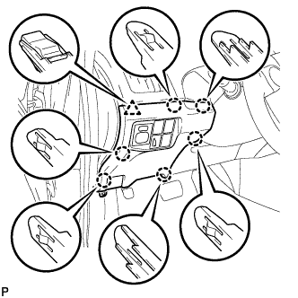
![]() |
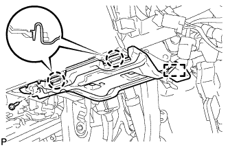
Engage the 6 claws and clip.
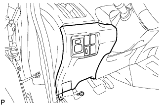
![]() |
Install the lower instrument panel finish panel assembly with the screw <C>.
| 12. INSTALL COWL SIDE TRIM SUB-ASSEMBLY LH (for LHD) |
![]() |
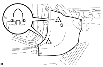
Engage the 2 clips.
Install the cowl side trim board LH with the clip.
| 13. INSTALL FRONT DOOR SCUFF PLATE LH (for LHD) |
![]() |
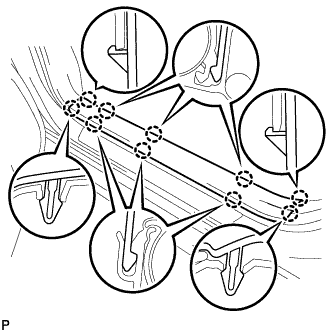
Engage the 10 claws to install the front door scuff plate LH.
| 14. INSTALL NO. 1 INSTRUMENT PANEL UNDER COVER SUB-ASSEMBLY (for RHD) |
Connect each connector.
![]() |
Engage the guide and 2 claws.
Install the No. 1 instrument panel under cover sub-assembly with the screw <D>.
| 15. INSTALL REAR WHEEL |
| 16. CONNECT CABLE TO NEGATIVE BATTERY TERMINAL |
Connect the cable to the negative (-) battery terminal.
Connect the reservoir level switch connector.
Clear the DTCs (Click here).
| 17. CHECK FOR SPEED SENSOR SIGNAL |