Inspect the fuel sender gauge assembly resistance.
Measure the resistance according to the value(s) in the table below.
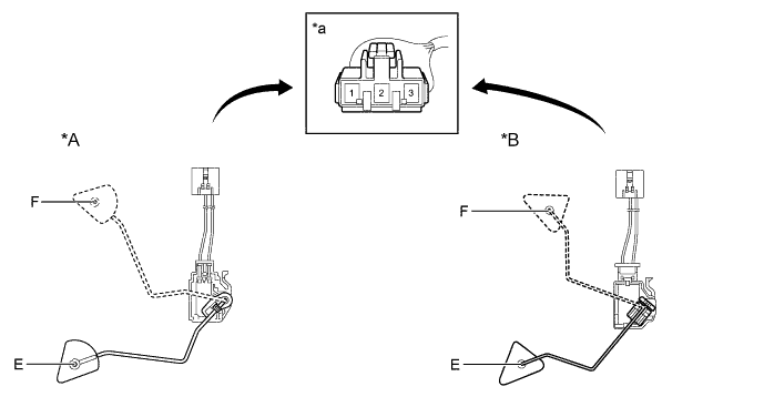
Text in Illustration *A Type A *B Type B *a Component without wire harness connected
(Fuel Sender Gauge Assembly)- - - Standard Resistance:
Tester Connection Float Level Specified Condition (Type A) Specified Condition (Type B) 1 - 2 F 13.5 to 16.5 Ω 12.0 to 18.0 Ω Between F and E 13.5 to 414.5 Ω (Gradually changes) 12.0 to 415.0 Ω (Gradually changes) E 405.5 to 414.5 Ω 405.0 to 415.0 Ω