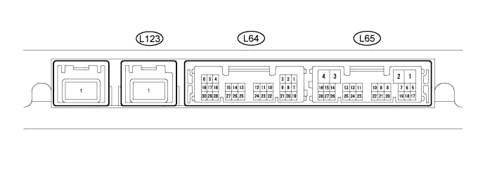
INTELLIGENT PARKING ASSIST SYSTEM > TERMINALS OF ECU |
| PARKING ASSIST ECU |
Disconnect the L65 connector from the parking assist ECU.
Measure the voltage and resistance of each terminal of the wire harness side connector.
| Terminal No. (Symbol) | Wiring Color | Terminal Description | Condition | Specified Condition |
| L65-1 (+B) - L65-3 (GND1) | SB - W-B | Power source signal | Always | 11 to 14 V |
| L65-3 (GND1) - Body ground | W-B - Body ground | Ground | Always | Below 1 Ω |
| L65-7 (IG) - L65-3 (GND1) | B - W-B | IG power source signal | Power switch on (IG) | 11 to 14 V |
| L65-8 (ACC) - L65-3 (GND1) | GR - W-B | ACC power source signal | Power switch on (ACC) | 11 to 14 V |
Reconnect the L65 connector to the ECU.
Measure the voltage and resistance, and check for pulses according to the value(s) in the table below.
| Terminal No. (Symbol) | Wiring Color | Terminal Description | Condition | Specified Condition |
| L64-11 (CV-) - L65-3 (GND1) | B - W-B | Rear television camera ground | Always | Below 1 V |
| L64-12 (CV+) - L65-3 (GND1) | R - W-B | Rear television camera display signal (NTSC) input | Power switch on (IG) Shift lever in R Under normal conditions | Pulse generation (See waveform 1) |
| Power switch on (IG) Shift lever in R Camera lens is covered, blacking out screen | Pulse generation (See waveform 2) | |||
| L64-13 (CGND) - L65-3 (GND1) | Shield - W-B | Rear television camera ground (shield) | Always | Below 1 V |
| L64-14 (CB+) - L65-3 (GND1) | W - W-B | Power source to rear television camera | Power switch on (IG) Shift lever in R | 5.8 to 7.0 V |
| L64-19 (CSB3) - L65-3 (GND1) | G - W-B | Power source to ultrasonic sensor | Power switch on (IG) | 7 to 9 V |
| L64-20 (CSG3) - L65-3 (GND1) | R - W-B | Ultrasonic sensor ground | Always | Below 1 Ω |
| L64-21 (LIN3) | GR | Ultrasonic sensor signal input and output | - | - |
| L65-11 (ISSW) - L65-3 (GND1) | L - W-B | Parking assist pre support signal input | Power switch on (IG) Parking assist pre support switch pushed in | Below 1 V |
| Power switch on (IG) Parking assist pre support switch not pushed | 4.75 to 5.25 V | |||
| L65-21 (CANL) - L65-3 (GND1) | BR - W-B | CAN communication signal | CAN communication circuit | Pulse generation |
| L65-22 (CANH) - L65-3 (GND1) | Y - W-B | CAN communication signal | CAN communication circuit | Pulse generation |
| L65-24 (TX-) - L65-25 (TX+) | P - LG | AVC-LAN communication signal | - | - |
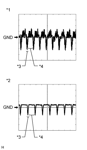 |
Reference (Oscilloscope waveform):
Waveform 1 (under normal conditions)
| Item | Content |
| Terminal No. (Symbol) | L64-12 (CV+) - L65-3 (GND1) |
| Tool Setting | 200 mV/DIV., 50 μsec./DIV. |
| Condition | Power switch on (IG), shift lever in R |
Waveform 2 (camera lens is covered, blacking out the screen)
| Item | Content |
| Terminal No. (Symbol) | L64-12 (CV+) - L65-3 (GND1) |
| Tool Setting | 200 mV/DIV., 50 μsec./DIV. |
| Condition | Power switch on (IG), shift lever in R |
| *1 | Waveform 1 (under normal conditions) |
| *2 | Waveform 2 (camera lens is covered, blacking out the screen) |
| *3 | Synchronized Signal |
| *4 | Video Waveform |
| REAR TELEVISION CAMERA ASSEMBLY |

Disconnect the V6 connector from the rear television camera assembly.
Measure the voltage of each terminal of the wire harness side connector.
| Terminal No. (Symbol) | Wiring Color | Terminal Description | Condition | Specified Condition |
| V6-3 (CGND) - Body ground | W-B - Body ground | Ground | Always | Below 1 V |
| V6-4 (CB+) - V6-3 (CGND) | W - W-B | Power source | Power switch on (IG) Shift lever in R | 5.8 to 7.0 V |
Reconnect the V6 connector to the rear television camera assembly.
Check for pulses according to the value(s) in the table below.
| Terminal No. (Symbol) | Wiring Color | Terminal Description | Condition | Specified Condition |
| V6-2 (CV+) - V6-1 (CV-) | R - B | Display signal | Power switch on (IG) Shift lever in R Under normal conditions | Pulse generation (See waveform 1) |
| Power switch on (IG) Shift lever in R Camera lens covered, blacking out screen | Pulse generation (See waveform 2) |
|
Reference (Oscilloscope waveform):
Waveform 1 (under normal conditions)
| Item | Content |
| Terminal No. (Symbol) | V6-2 (CV+) - V6-1 (CV-) |
| Tool Setting | 200 mV/DIV., 50 μsec./DIV. |
| Condition | Power switch on (IG), shift lever in R |
Waveform 2 (camera lens is covered, blacking out the screen)
| Item | Content |
| Terminal No. (Symbol) | V6-2 (CV+) - V6-1 (CV-) |
| Tool Setting | 200 mV/DIV., 50 μsec./DIV. |
| Condition | Power switch on (IG), shift lever in R |
| *1 | Waveform 1 (under normal conditions) |
| *2 | Waveform 2 (camera lens is covered, blacking out the screen) |
| *3 | Synchronized Signal |
| *4 | Video Waveform |
| NAVIGATION RECEIVER ASSEMBLY (for HDD) (Click here) |
| NAVIGATION RECEIVER ASSEMBLY (for DVD) (Click here) |