 |
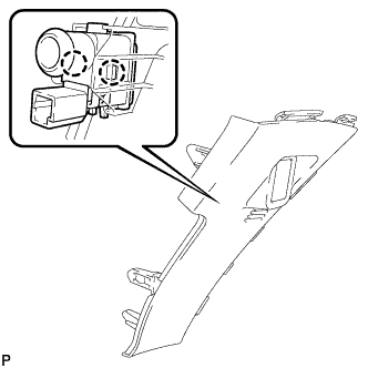
Engage the 2 claws to install the room temperature sensor to the No. 1 switch hole base.
ROOM TEMPERATURE SENSOR > INSTALLATION |
| 1. INSTALL ROOM TEMPERATURE SENSOR |
|
Engage the 2 claws to install the room temperature sensor to the No. 1 switch hole base.
| 2. INSTALL NO. 1 SWITCH HOLE BASE |
Connect the connector.
Engage the 5 claws to install the No. 1 switch hole base.
| 3. INSTALL UPPER INSTRUMENT PANEL FINISH PANEL ASSEMBLY |
Temporarily install the console box assembly.
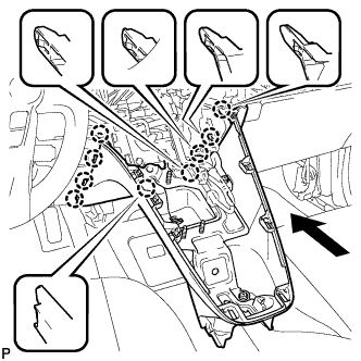 |
Engage the 9 claws as shown in the illustration.
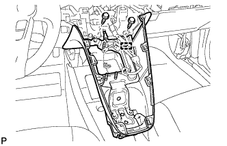 |
Install the to install the upper instrument panel finish panel assembly with the 2 bolts <A>.
Engage the clamp.
| 4. INSTALL SHIFT LOCK CONTROL UNIT ASSEMBLY |
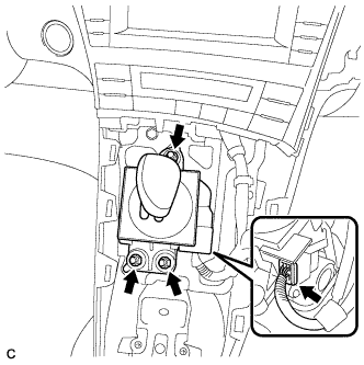 |
Install the shift lock control unit assembly with the 3 nuts.
Connect the connector to the shift lock control unit assembly.
| 5. INSTALL AIR CONDITIONING CONTROL ASSEMBLY |
Connect the connector.
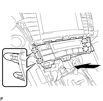 |
Engage the 4 claws to install the air conditioning control assembly.
| 6. INSTALL CONSOLE BOX ASSEMBLY |
Connect each connector.
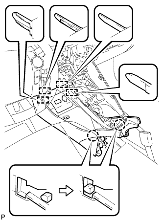 |
Engage the 4 guides and 2 claws as shown in the illustration.
Install the console box assembly with the bolt <B> and 2 clips.
| 7. INSTALL BOX BOTTOM MAT |
Engage the fastener to install the box bottom mat.
| 8. INSTALL FRONT NO. 2 CONSOLE BOX INSERT |
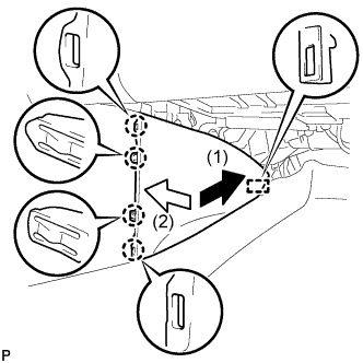 |
Engage the guide and 4 claws to install the front No. 2 console box insert as shown in the illustration.
| 9. INSTALL FRONT NO. 1 CONSOLE BOX INSERT |
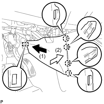 |
Engage the guide and 4 claws to install the front No. 1 console box insert as shown in the illustration.
| 10. INSTALL NO. 2 CONSOLE BOX MOUNTING BRACKET |
Install the No. 2 console box mounting bracket with the 6 bolts <B>.
| 11. INSTALL ELECTRICAL KEY OSCILLATOR |
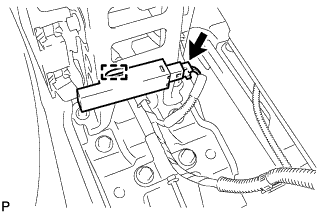 |
Engage the clamp and install the electrical key oscillator.
Connect the connector.
| 12. INSTALL REAR CONSOLE BOX ASSEMBLY |
Connect each connector.
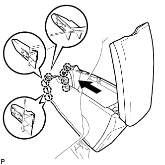 |
Engage the 8 claws as shown in the illustration.
Install the rear console box assembly with the 5 bolts.
| 13. INSTALL CONSOLE BOX CARPET |
Install the console box carpet.
| 14. INSTALL REAR CONSOLE BOX CUP HOLDER |
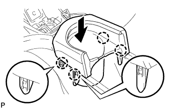 |
Engage the 4 claws to install the rear console box cup holder as shown in the illustration.
| 15. INSTALL UPPER INSTRUMENT PANEL FINISH PANEL SUB-ASSEMBLY |
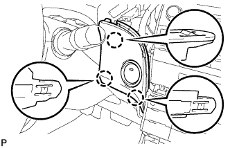 |
Connect the connector.
Engage the 3 claws to install the upper instrument panel finish panel sub-assembly.
| 16. INSTALL INSTRUMENT CLUSTER FINISH PANEL GARNISH |
Connect the connector.
Engage the 14 claws to install the instrument cluster finish panel garnish.
| 17. INSTALL LOWER CENTER INSTRUMENT CLUSTER FINISH PANEL SUB-ASSEMBLY |
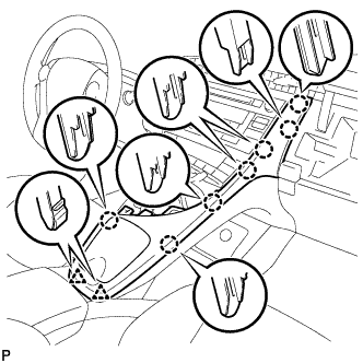 |
Engage the 7 claws and 2 clips to install the lower center instrument cluster finish panel sub-assembly.
| 18. INSTALL INTEGRATION CONTROL AND PANEL ASSEMBLY |
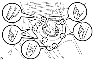 |
Connect each connector.
Engage the 6 claws to install the integration control and panel assembly.
| 19. INSPECT SHIFT LEVER |
Turn the power switch on (READY).
Check that all available shift positions can be selected moving the shift lever.