 |
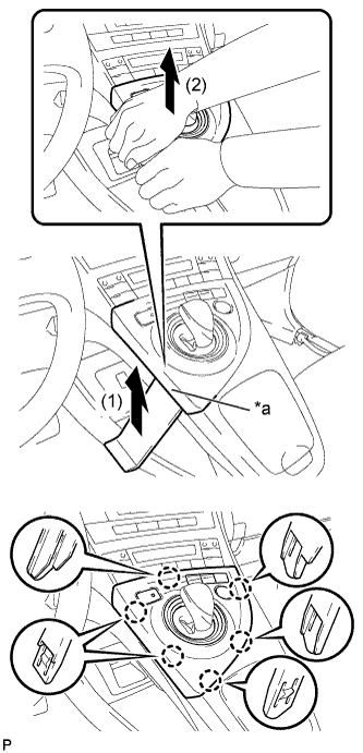
Using a moulding remover, slightly lift the panel at the position shown in the illustration.
| *a | Lift slightly |
NAVIGATION RECEIVER > REMOVAL |
| 1. PRECAUTION (w/ Navigation System for HDD) |
| 2. EJECT MAP DISC (w/ Navigation System for DVD) |
for LHD:
Turn the power switch to ACC.
Push the "INFO" button.
Touch "Map Data" on the navigation screen.
Touch "EJECT DVD" on the navigation screen to eject the map disc.
Turn the power switch off.
for RHD:
Turn the power switch to ACC.
Push the "OPEN" button.
Push the "MAP" button to eject the map disc.
| 3. REMOVE INTEGRATION CONTROL AND PANEL ASSEMBLY |
|
Using a moulding remover, slightly lift the panel at the position shown in the illustration.
| *a | Lift slightly |
Pull the integration control and panel assembly in the direction indicated by the arrow to disengage the 6 claws.
Disconnect each connector and remove the integration control and panel assembly.
| 4. REMOVE LOWER CENTER INSTRUMENT CLUSTER FINISH PANEL SUB-ASSEMBLY |
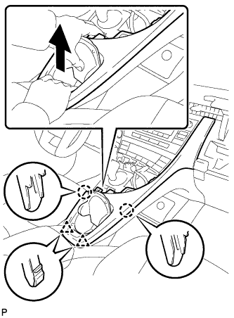 |
Pull the lower center instrument cluster finish panel sub-assembly in the direction indicated by the arrow to disengage the 2 claws and 2 clips.
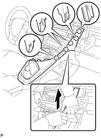 |
Pull the lower center instrument cluster finish panel sub-assembly in the direction indicated by the arrow to disengage the 5 claws and remove the lower center instrument cluster finish panel sub-assembly.
| 5. REMOVE INSTRUMENT CLUSTER FINISH PANEL GARNISH |
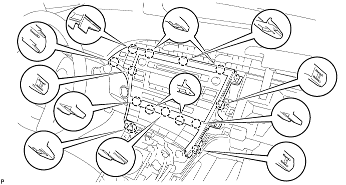
Disengage the 14 claws.
Disconnect the connector and remove the instrument cluster finish panel garnish.
| 6. REMOVE UPPER INSTRUMENT PANEL FINISH PANEL SUB-ASSEMBLY |
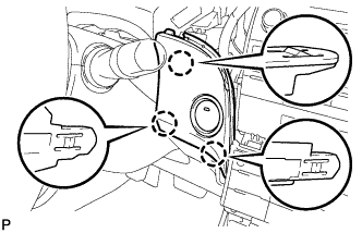 |
Disengage the 3 claws.
Disconnect the connector and remove the upper instrument panel finish panel sub-assembly.
| 7. REMOVE NAVIGATION RECEIVER WITH BRACKET |
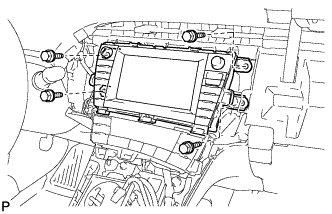 |
Remove the 4 bolts.
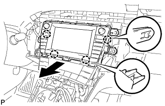 |
Disengage the 4 claws and remove the navigation receiver assembly with bracket as shown in the illustration.
Disconnect each connector.
| 8. REMOVE NO. 2 RADIO BRACKET |
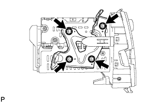 |
Remove the 4 screws and No. 2 radio bracket.
| 9. REMOVE NO. 1 RADIO BRACKET |
| 10. REMOVE NAVIGATION RECEIVER ASSEMBLY |