 |
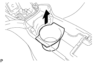
Remove the rear console box pocket.
LOWER INSTRUMENT PANEL > REMOVAL |
| 1. PRECAUTION |
| 2. REMOVE UPPER INSTRUMENT PANEL ASSEMBLY |
Remove the upper instrument panel assembly (Click here).
| 3. REMOVE REAR CONSOLE BOX POCKET |
|
Remove the rear console box pocket.
| 4. REMOVE UPPER CONSOLE PANEL |
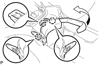 |
Using a moulding remover, disengage the 3 claws to remove the upper console panel as shown in the illustration.
| 5. REMOVE CONSOLE BOX CARPET |
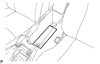 |
Remove the console box carpet.
| 6. REMOVE REAR CONSOLE BOX ASSEMBLY |
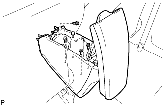 |
Remove the 5 bolts.
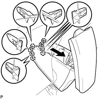 |
Pull the rear console box assembly in the direction indicated by the arrow to disengage the 8 claws.
Disconnect the connector and remove the rear console box assembly.
| 7. REMOVE ELECTRICAL KEY OSCILLATOR |
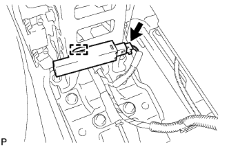 |
Disconnect the connector.
Disengage the clamp and remove the electrical key oscillator.
| 8. REMOVE NO. 2 CONSOLE BOX MOUNTING BRACKET |
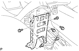 |
Remove the 6 bolts <B> and No. 2 console box mounting bracket.
| 9. REMOVE FRONT NO. 1 CONSOLE BOX INSERT |
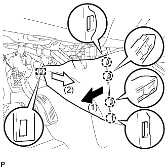 |
Pull the front No. 1 console box insert in the direction indicated by the arrow to disengage the 4 claws and guide, and remove the front No. 1 console box insert.
| 10. REMOVE FRONT NO. 2 CONSOLE BOX INSERT |
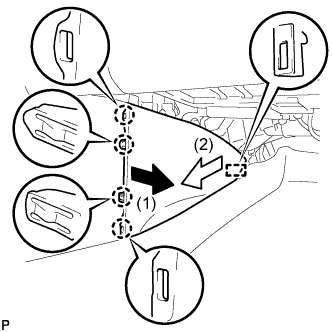 |
Pull the front No. 2 console box insert in the direction indicated by the arrow to disengage the 4 claws and guide, and remove the front No. 2 console box insert.
| 11. REMOVE BOX BOTTOM MAT |
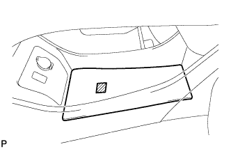 |
Disengage the fastener and remove the box bottom mat.
| 12. SEPARATE CONSOLE BOX ASSEMBLY |
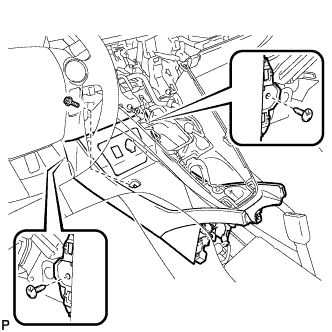 |
Remove the bolt <B> and 2 clips.
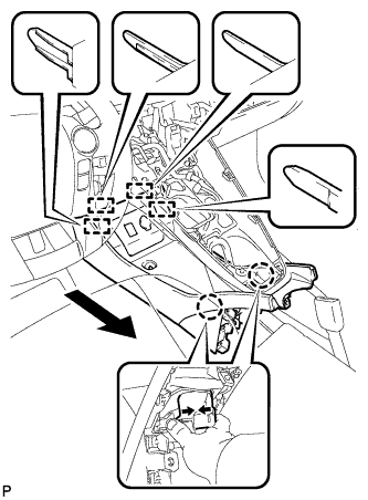 |
While pushing the parts shown in the illustration inward, pull the console box assembly in the direction indicated by the arrow to disengage the 2 claws and 4 guides.
Disconnect the connector and separate the console box assembly.
| 13. REMOVE AIR CONDITIONING CONTROL ASSEMBLY |
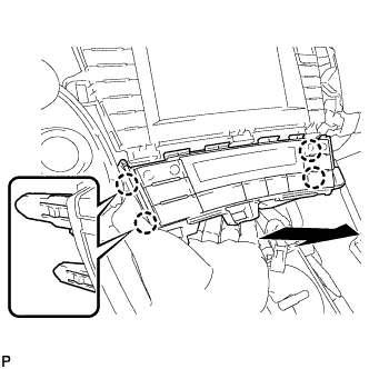 |
Disengage the 4 claws and remove the air conditioning control assembly as shown in the illustration.
Disconnect the connector.
| 14. REMOVE SHIFT LOCK CONTROL UNIT ASSEMBLY |
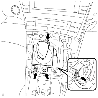 |
Disconnect the connector from the shift lock control unit assembly.
Remove the 3 nuts and shift lock control unit assembly.
| 15. REMOVE UPPER INSTRUMENT PANEL FINISH PANEL ASSEMBLY |
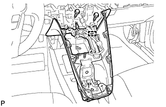 |
Disengage the clamp.
Remove the 2 bolts <A>.
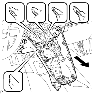 |
Pull the upper instrument panel finish panel assembly in the direction indicated by the arrow to disengage the 9 claws and remove the upper instrument panel finish panel assembly.
| 16. REMOVE CONSOLE BOX ASSEMBLY |
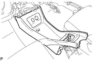 |
Remove the console box assembly.
| 17. REMOVE NO. 1 SWITCH HOLE BASE |
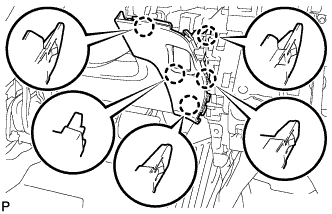 |
Disengage the 5 claws.
Disconnect the connector to remove the No. 1 switch hole base.
| 18. REMOVE LOWER STEERING COLUMN COVER |
Release the tilt and telescopic lever, and fully extend and lower the steering column assembly.
Lock the tilt and telescopic lever.
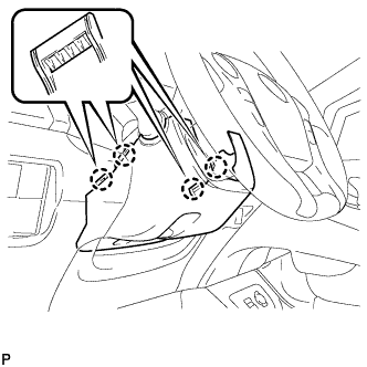 |
Push the right and left sides of the lower steering column cover to disengage the 4 claws.
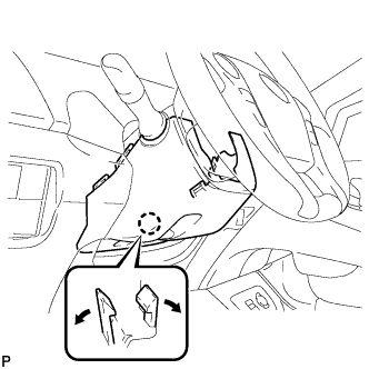 |
Insert fingers into the opening of the tilt lever of the lower steering column cover to disengage the claw.
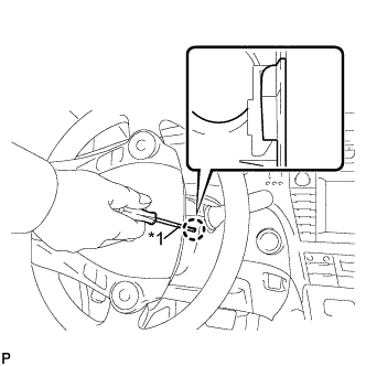 |
Turn the steering wheel assembly to the right.
| *1 | Protective Tape |
Using a screwdriver, disengage the claw as shown in the illustration.
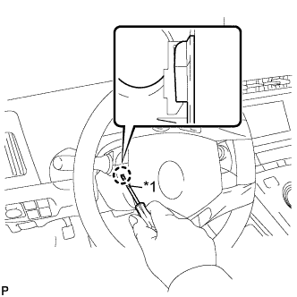 |
Turn the steering wheel assembly to the left.
| *1 | Protective Tape |
Using a screwdriver, disengage the claw as shown in the illustration.
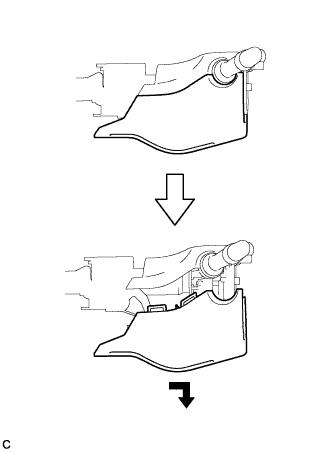 |
Remove the lower steering column cover as shown in the illustration.
| 19. REMOVE UPPER STEERING COLUMN COVER |
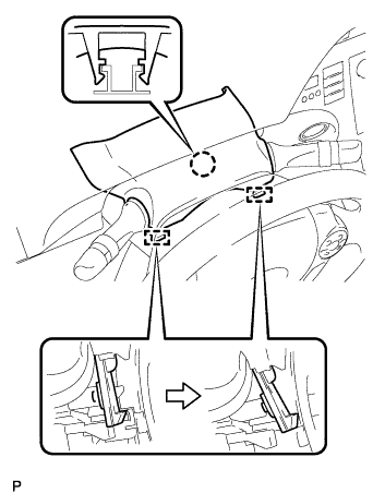 |
Disengage the claw and 2 pins, and remove the upper steering column cover.
| 20. REMOVE NO. 1 INSTRUMENT PANEL UNDER COVER SUB-ASSEMBLY (for LHD) |
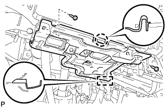 |
Remove the 2 screws <D>.
Disengage the claw and guide.
Disconnect each connector and remove the No. 1 instrument panel under cover sub-assembly.
| 21. REMOVE NO. 1 INSTRUMENT PANEL UNDER COVER SUB-ASSEMBLY (for RHD) |
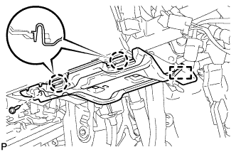 |
Remove the screw <D>.
Disengage the 2 claws and guide.
Disconnect each connector and remove the No. 1 instrument panel under cover sub-assembly.
| 22. REMOVE DRIVER SIDE KNEE AIRBAG ASSEMBLY |
Check that the power switch is off.
Check that the cable is disconnected from the negative (-) battery terminal.
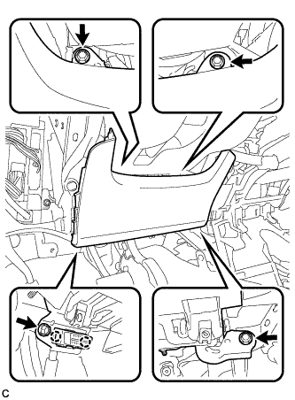 |
Remove the 4 bolts.
Disengage the 2 claws to separate the DLC3.
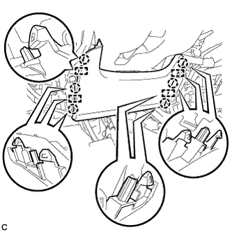 |
Disengage the 6 claws and 4 guides to separate the driver side knee airbag assembly.
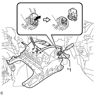 |
Disengage the clamp to separate the wire harness.
Using a screwdriver with the tip wrapped with protective tape, release the airbag connector lock.
| *1 | Protective Tape |
Disconnect the airbag connector to remove the driver side knee airbag assembly.
| 23. REMOVE NO. 2 INSTRUMENT PANEL UNDER COVER SUB-ASSEMBLY |
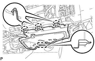 |
Disengage the 3 claws and guide.
Disconnect each connector and remove the No. 2 instrument panel under cover sub-assembly.
| 24. REMOVE GLOVE COMPARTMENT DOOR ASSEMBLY |
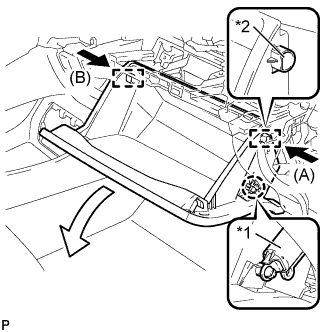 |
Disengage the claw and release the glove compartment door stopper.
| *1 | Glove Compartment Door Stopper Sub-assembly |
| *2 | Stopper |
Slightly bend stoppers (A) and (B) in the directions indicated by the arrows in the illustration and pull the glove compartment door assembly until the stoppers are released.
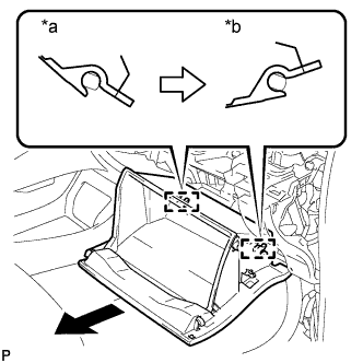 |
Open the glove compartment door assembly to approximately 55° from its closed position. Pull it horizontally in the direction indicated by the arrow to disengage the 2 hinges and remove the glove compartment door assembly.
| *a | Close |
| *b | Open Approximately |
| 25. REMOVE GLOVE COMPARTMENT DOOR STOPPER SUB-ASSEMBLY |
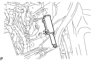 |
Disengage the claw to remove the glove compartment door stopper sub-assembly.
| 26. REMOVE FRONT DOOR SCUFF PLATE RH |
| 27. REMOVE COWL SIDE TRIM SUB-ASSEMBLY RH |
| 28. REMOVE NO. 1 HEATER TO REGISTER DUCT |
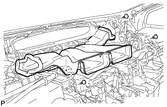 |
Remove the 3 clips and the No. 1 heater to register duct.
| 29. REMOVE COMBINATION METER ASSEMBLY |
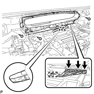 |
Disconnect the 3 connectors.
Disengage the clamp.
Remove the 3 screws.
Disengage the clip and remove the combination meter assembly.
| 30. REMOVE POWER STEERING ECU ASSEMBLY |
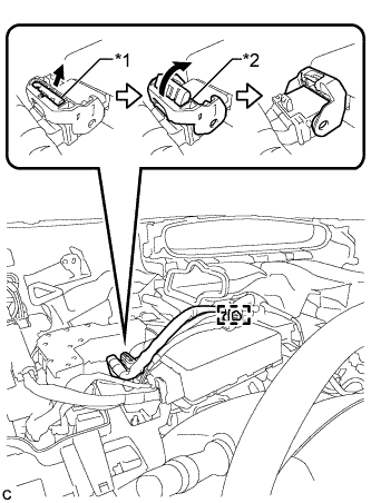 |
Disengage the wire harness clamp from the power steering ECU assembly.
| *1 | Lock of the Lock Lever |
| *2 | Lock Lever |
Disconnect the connector from the power steering ECU assembly.
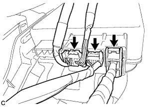 |
Disconnect the 3 connectors from the power steering ECU assembly.
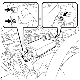 |
Remove the bolt, 2 nuts, and the power steering ECU assembly.
| 31. REMOVE INSTRUMENT PANEL SAFETY PAD PLATE SUB-ASSEMBLY (for LHD) |
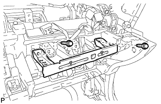 |
Remove the 2 bolts <B> and instrument panel safety pad plate sub-assembly.
| 32. REMOVE GLOVE COMPARTMENT DOOR LOCK ASSEMBLY |
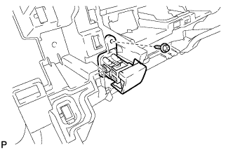 |
Remove the screw <D> and glove compartment door lock assembly.
| 33. REMOVE GLOVE BOX LIGHT ASSEMBLY |
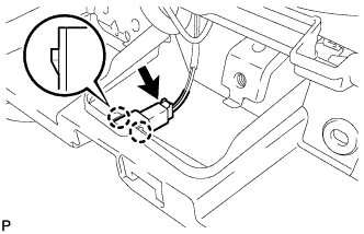 |
Disconnect the connector.
Using a screwdriver, disengage the 2 claws and remove the glove box light assembly.
| 34. REMOVE NO. 2 ANTENNA CORD SUB-ASSEMBLY (for LHD) |
for Connector Type Antenna Cord:
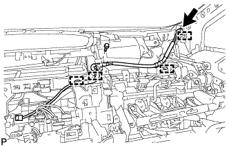 |
Disconnect the connector.
Remove the bolt.
Disengage the 4 clamps and remove the No. 2 antenna cord sub-assembly.
for Plug Type Antenna Cord:
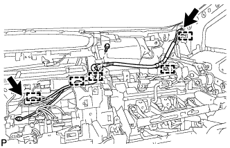 |
Disconnect the 2 connectors.
Remove the bolt.
Disengage the 5 clamps and remove the No. 2 antenna cord sub-assembly.
| 35. REMOVE NO. 2 ANTENNA CORD SUB-ASSEMBLY (for RHD) |
for Connector Type Antenna Cord:
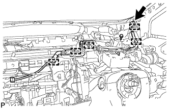 |
Disconnect the connector.
Remove the bolt.
Disengage the 5 clamps and remove the No. 2 antenna cord sub-assembly.
for Plug Type Antenna Cord:
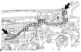 |
Disconnect the 2 connectors.
Remove the bolt.
Disengage the 6 clamps and remove the No. 2 antenna cord sub-assembly.
| 36. REMOVE LOWER INSTRUMENT PANEL SUB-ASSEMBLY (for LHD) |
Disengage each clamp.
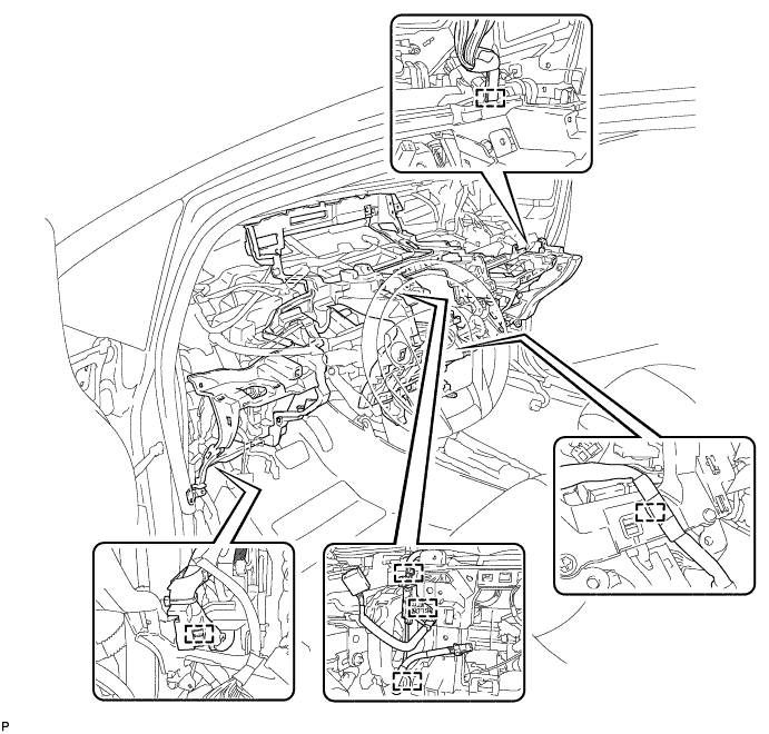
Remove the 4 bolts <B>, 11 bolts <C> and screw <D> and lower instrument panel sub-assembly.
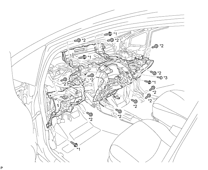
| *1 | Bolt <B> | *2 | Bolt <C> |
| *3 | Screw <D> | - | - |
| 37. REMOVE LOWER INSTRUMENT PANEL SUB-ASSEMBLY (for RHD) |
Disengage the 2 claws.
Disengage each clamp.
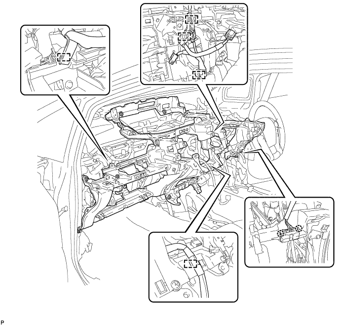
Remove the 4 bolts <B>, 11 bolts <C> and screw <D> and lower instrument panel sub-assembly.
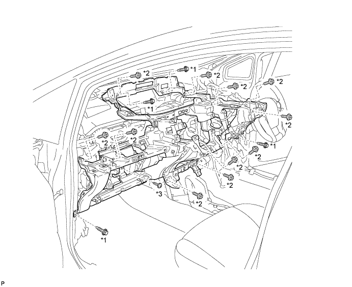
| *1 | Bolt <B> | *2 | Bolt <C> |
| *3 | Screw <D> | - | - |