Home › Steering › STEERING COLUMN › STEERING PAD SWITCH

STEERING PAD SWITCH > INSPECTION

for Preparation Click here


1. INSPECT STEERING PAD SWITCH LH


  1. Measure the resistance according to the value(s) in the table below.
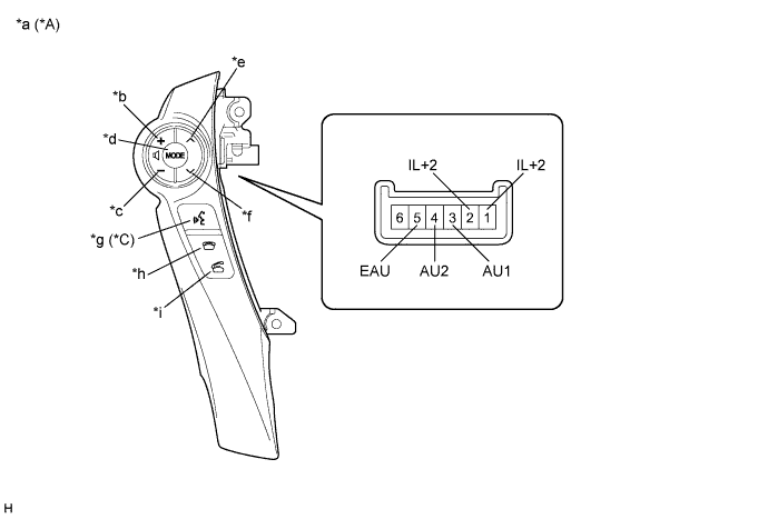
    E250472E03


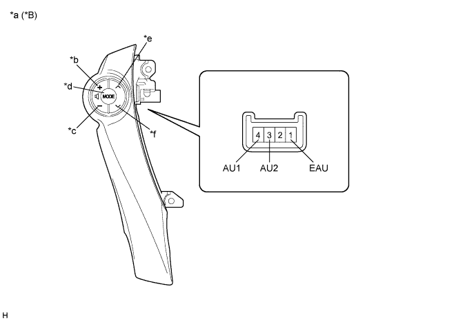
    E256158E01


    Standard Resistance:
    w/ Touch Tracer Display 
    Tester Connection
    Condition
    Specified Condition
    1 (IL+2) - 2 (IL+2)
    No switch pushed
    Below 1 Ω
    3 (AU1) - 5 (EAU)
    No switch pushed
    95 to 105 kΩ
    Seek+ switch pushed
    Below 2.5 Ω
    Seek- switch pushed
    323 to 335 Ω
    Volume+ switch pushed
    980 to 1020 Ω
    Volume- switch pushed
    3048 to 3172 Ω
    4 (AU2) - 5 (EAU)
    No switch pushed
    95 to 105 kΩ
    MODE switch pushed
    Below 2.5 Ω
    On hook switch pushed
    323 to 335 Ω
    Off hook switch pushed
    980 to 1020 Ω
    Voice switch pushed*1
    3048 to 3172 Ω
    w/o Touch Tracer Display 
    Tester Connection
    Condition
    Specified Condition
    4 (AU1) - 1 (EAU)
    No switch pushed
    95 to 105 kΩ
    Seek+ switch pushed
    Below 2.5 Ω
    Seek- switch pushed
    323 to 335 Ω
    Volume+ switch pushed
    980 to 1020 Ω
    Volume- switch pushed
    3048 to 3172 Ω
    3 (AU2) - 1 (EAU)
    No switch pushed
    95 to 105 kΩ
    MODE switch pushed
    Below 2.5 Ω

    1. *1: w/ Voice Switch of Steering Pad Switch LH

    HINT:
    If the result is not as specified, replace the steering pad switch LH.


    Text in Illustration 
    *A
    w/ Touch Tracer Display
    *B
    w/o Touch Tracer Display
    *C
    w/ Voice Switch of Steering Pad Switch LH
    -
    -
    *a
    Component without harness connected
    (Steering Pad Switch LH)
    *b
    Volume+
    *c
    Volume-
    *d
    MODE
    *e
    Seek+
    *f
    Seek-
    *g
    Voice
    *h
    On hook
    *i
    Off hook
    -
    -


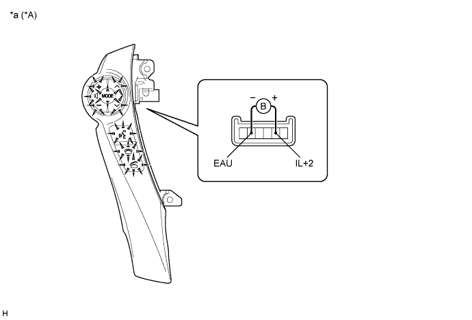
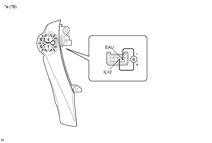
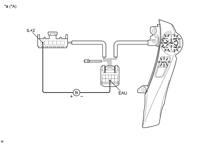
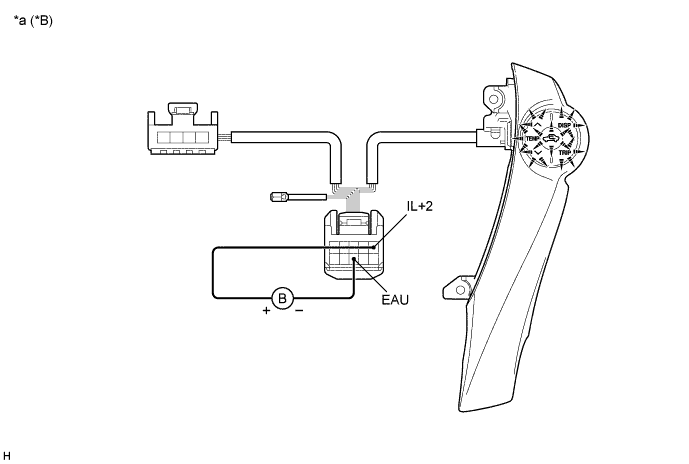
  1. Check the illumination.


    E250473E02


    E256159E01


    1. Connect an auxiliary battery positive (+) lead to terminal IL+2 and a negative (-) lead to terminal EAU of the steering pad switch LH connector.

    2. Check that the switch illumination comes on.

      OK:
      Steering pad switch illumination comes on.

      HINT:
      If the result is not as specified, replace the steering pad switch LH.


      Text in Illustration 
      *A
      w/ Touch Tracer Display
      *B
      w/o Touch Tracer Display
      *a
      Component without harness connected
      (Steering Pad Switch LH)
      -
      -


2. INSPECT STEERING PAD SWITCH RH


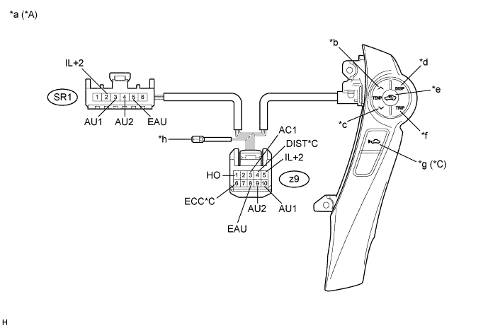
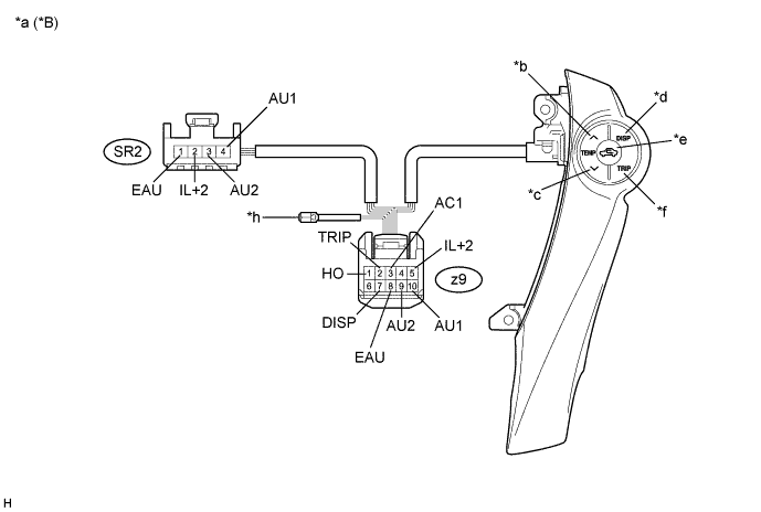
  1. Measure the resistance according to the value(s) in the table below.


    E250470E14


    E256130E04


    Standard Resistance:
    w/ Touch Tracer Display 
    Tester Connection
    Condition
    Specified Condition
    z9-1 (HO) - Terminal-A
    Always
    Below 1 Ω
    z9-3 (AC1) - z9-8 (EAU)
    No switch pushed
    95 to 105 kΩ
    R/F switch pushed
    323 to 335 Ω
    TEMP+ switch pushed
    980 to 1020 Ω
    TEMP- switch pushed
    3048 to 3172 Ω
    z9-4 (DIST) - z9-6 (ECC)*1
    No switch pushed
    1 MΩ or higher
    Distance control switch pushed
    Below 2.5 Ω
    SR1-2 (IL+2) - z9-5 (IL+2)
    Always
    Below 1 Ω
    SR1-3 (AU1) - z9-10 (AU1)
    Always
    Below 1 Ω
    SR1-4 (AU2) - z9-9 (AU2)
    Always
    Below 1 Ω
    SR1-5 (EAU) - z9-8 (EAU)
    Always
    Below 1 Ω
    w/o Touch Tracer Display 
    Tester Connection
    Condition
    Specified Condition
    z9-1 (HO) - Terminal-A
    Always
    Below 1 Ω
    z9-2 (TRIP) - z9-8 (EAU)
    TRIP switch pushed
    Below 2.5 Ω
    z9-3 (AC1) - z9-8 (EAU)
    No switch pushed
    95 to 105 kΩ
    R/F switch pushed
    323 to 335 Ω
    TEMP+ switch pushed
    980 to 1020 Ω
    TEMP- switch pushed
    3048 to 3172 Ω
    z9-7 (DISP) - z9-8 (EAU)
    DISP switch pushed
    Below 2.5 Ω
    SR2-2 (IL+2) - z9-5 (IL+2)
    Always
    Below 1 Ω
    SR2-4 (AU1) - z9-10 (AU1)
    Always
    Below 1 Ω
    SR2-3 (AU2) - z9-9 (AU2)
    Always
    Below 1 Ω
    SR2-1 (EAU) - z9-8 (EAU)
    Always
    Below 1 Ω

    1. *1: w/ Distance Control Switch of Steering Pad Switch RH

    HINT:
    If the result is not as specified, replace the steering pad switch RH.


    Text in Illustration 
    *A
    w/ Touch Tracer Display
    *B
    w/o Touch Tracer Display
    *C
    w/ Distance Control Switch of Steering Pad Switch RH
    -
    -
    *a
    Component without harness connected
    (Steering Pad Switch RH)
    *b
    TEMP+
    *c
    TEMP-
    *d
    DISP
    *e
    R/F
    *f
    TRIP
    *g
    Distance control
    *h
    Terminal-A


  1. Check the illumination.


    E250471E03


    E256131E01


    1. Connect an auxiliary battery positive (+) lead to terminal IL+2 and a negative (-) lead to terminal EAU of the steering pad switch RH connector.

    2. Check that the switch illumination comes on.

      OK:
      Steering pad switch illumination comes on.

      HINT:
      If the result is not as specified, replace the steering pad switch RH.


      Text in Illustration 
      *A
      w/ Touch Tracer Display
      *B
      w/o Touch Tracer Display
      *a
      Component without harness connected
      (Steering Pad Switch RH)
      -
      -