METER / GAUGE SYSTEM > DETAILS |
| OPERATING CONDITION |
Eco Driving Indicator Light Operation Condition
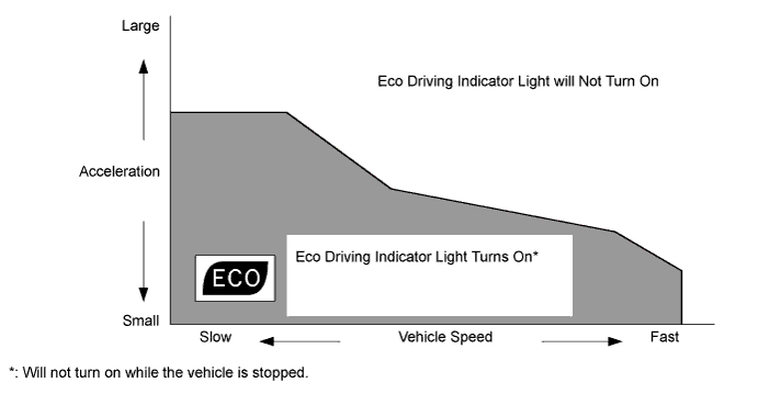
When all of the following conditions are met, the power management control ECU and meter ECU determine that Eco-friendly driving is being performed and turn on Eco Driving Indicator Light. However, if one of them fails, the power management control ECU and meter ECU turn off Eco Driving Indicator Light.
| Condition |
|
Hybrid System Indicator Operation Condition
Hybrid System Indicator is activated when the following conditions are met.
| Condition |
|
| SYSTEM CONTROL |
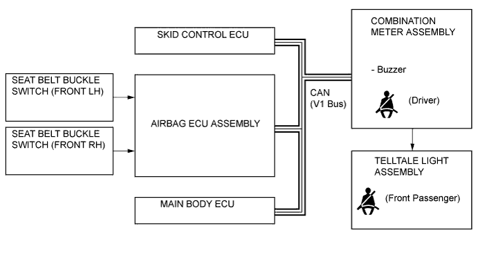
Seat Belt Warning
The seat belt warning light blinks if the driver seat belt is not fastened when the power switch is turned on (IG), and at the same time, the buzzer sounds intermittently 5 times. However, after that, if the seat belt is still not fastened and the vehicle speed exceeds approximately 20 km/h (12.4 mph), the buzzer again sounds intermittently for approximately 9.6 seconds. During this time, the buzzer sounds loudly and the seat belt warning light blinks at short intervals after approximately 20 seconds have elapsed since the buzzer sounded.

| FUNCTION |
Combination Meter
The table below shows the combination meter function:
| Display Item | Outline |
| Fuel Gauge Display | Displays the remaining fuel amount. Also, it is capable of displaying the indication accurately when cornering or driving on a steep slope by using a software application capable of suppressing any indication deviations. |
| Speedometer | Digitally displays the vehicle speed signal in MPH or km/h. |
| Instantaneous Fuel Consumption Display | Displays the instantaneous fuel consumption, which is calculated by the combination meter assembly based on the vehicle speed and the amount of fuel used. |
| Shift Position Display | Displays the shift position. |
Multi-information Display
The table below shows the multi-information display function:
| Display | Display Item | Outline |
![]() | Remaining battery amount | Displays the remaining HV battery amount in 8 levels according to the signal from the power management control ECU. |
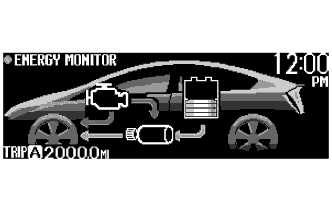
![]() | Energy Monitor |
|
![]() | Eco Driving Indicator Light | Receives the signal from the power management control ECU and meter ECU during vehicle operation and turns on/off the indicator depending on the situation, whether Eco-friendly acceleration is being performed or not. |
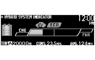
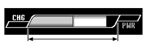
![]() | Hybrid System Indicator | Hybrid System Indicator displays the system power output and regenerative charging of the hybrid system. |
![]() | Charge area |
|
![]() | Hybrid Eco area |
|
![]() | Eco area |
|
![]() | Power area |
|
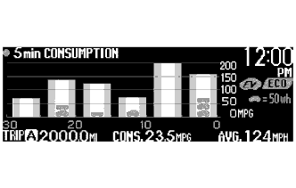
![]() | 5 min. Consumption Record | Displays the history of the average fuel consumption in 5 minute intervals on a bar graph. Displays the average recovered energy amount for 5 minutes using a symbol. |
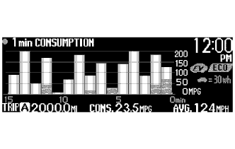
![]() | 1 min. Consumption Record | Displays the history of the average fuel consumption in 1 minute intervals on a bar graph. Displays the average recovered energy amount for 1 minute using a symbol. |
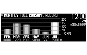
![]() | Monthly Fuel Consumption Record |
|
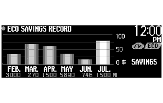
![]() | Eco Savings Record |
|
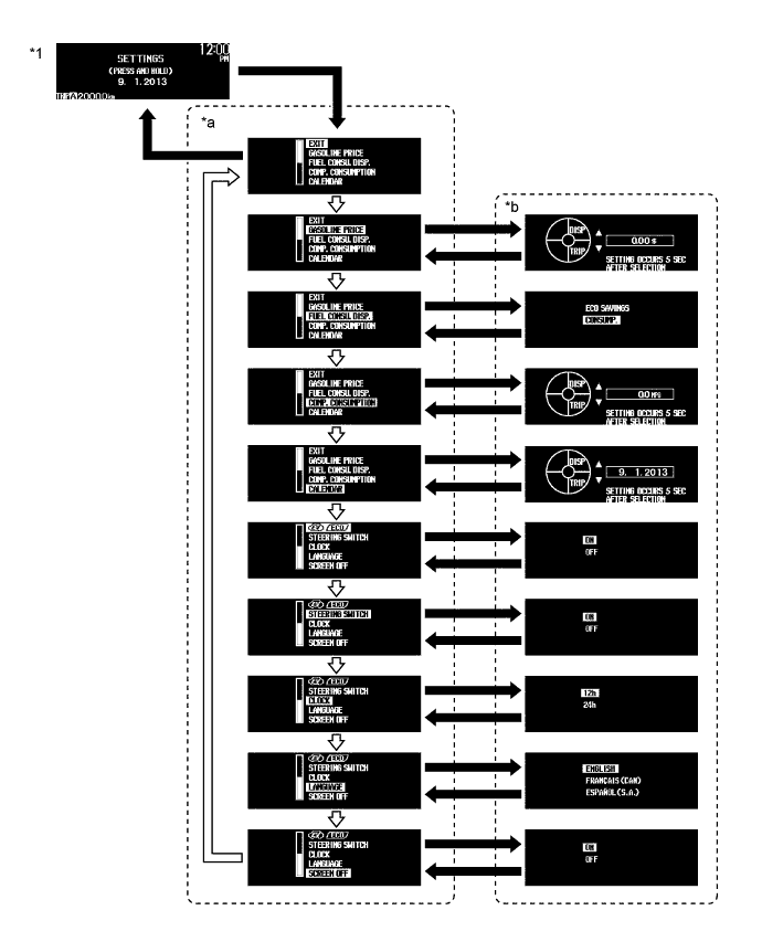
Custom Setting Function for Multi-information Display
When the vehicle speed is approximately 8 km (5 mph) or less, the display mode for the following 9 items can be used.
| Item | Customizing Value |
| GASOLINE PRICE | Inputs the gasoline price per 1 gal or 1 L. |
| FUEL CONSU. DISP. | Selects the monthly fuel consumption record and Eco saving record on/off mode. |
| COMP. CONSUMPTION | Inputs the value of the target fuel consumption. |
| CALENDAR | Adjusts the date. |
| EV / ECO | Selects the Eco Driving Indicator Light and EV Driving Indicator Light on/off mode. |
| STEERING SWITCH | Selects the touch tracer display on/off mode. |
| CLOCK | Selects the 12/24 hour time display mode. |
| LANGUAGE | Selects the display language. |
| SCREEN OFF | Turns on/off the multi-information display. |

| *1 | Setting Screen | - | - |
| *a | Setting Item Selection Screen | *b | Setting Selector Screen |
![]() | DISP Switch is Pressed Briefly. | ![]() | DISP Switch is Pressed and Held. |
Buzzer
The table below shows the warning functions of the buzzer in the combination meter assembly:
| Function | Item |
| Warning |
|
Warning Message
When a warning is necessary, the warning display interrupts the display in the multi-information display.
The master warning light may illuminate or blink and the buzzer in the combination meter assembly may sound depending on the item in the multi-information display.
| Priority | Warning Message | Master Warning Light | Buzzer |
| 1 | BRAKE! | - | - |
| 2 | AUTO POWER OFF TO CONSERVE BATTERY | - | - |
| 3 | SHIFT TO P POSITION | Blinks | Sounds |
| SHIFT TO P POSITION WHEN PARKED | Blinks | Sounds | |
| N POSITION | Blinks | Sounds | |
| DEPRESS BRAKE PEDAL WHEN VEHICLE IS AT A STANDSTILL | Blinks | Sounds | |
| TRACTION BATTERY PROTECTION MODE RESTART AFTER SHIFTING TO P POSITION | Blinks | Sounds | |
| TRACTION BATTERY POWER LOW CHARGE WHEN NOT IN N POSITION | Blinks | Sounds | |
| 4 | P LOCK MALFUNCTION WHEN PARKING, PARK IN FLAT PLACE AND APPLY PARKING BRAKE SECURELY | Illuminates | Sounds |
| CHECK HYBRID SYSTEM STOP THE VEHICLE IN A SAFE PLACE | Illuminates | Sounds | |
| CHECK BRAKE LAMP SYSTEM | Illuminates | Sounds | |
| 5 | KEY NOT DETECTED | Blinks | Sounds |
| 6 | SWITCHED TO N. TO SHIFT TO P, STOP CAR AND PRESS P SWITCH | Blinks | Sounds |
| CLEAN RADAR SENSOR | Illuminates | Sounds | |
| CRUISE CONTROL NOT AVAILABLE | Illuminates | Sounds | |
| 7 | CHECK CRUISE CONTROL SYSTEM | Illuminates | Sounds |
| CHECK PCS SYSTEM | Illuminates | Sounds | |
| CHECK LKA SYSTEM | Illuminates | Sounds | |
| LOW ENGINE OIL PRESSURE | Illuminates | Sounds | |
| 8 | TURN POWER OFF | Blinks | Sounds |
| SHIFT TO P POSITION AND PUSH POWER SWITCH TO TURN OFF | Blinks | Sounds | |
| KEY DETECTED IN VEHICLE | Blinks | Sounds | |
| DEPRESS BRAKE PEDAL, TOUCH POWER SWITCH WITH KEY | Blinks | Sounds | |
| DEPRESS BRAKE PEDAL AND PUSH POWER SWITCH TO START | Blinks | Sounds | |
| SHIFT TO P POSITION WHEN STARTING | Blinks | Sounds | |
| 9 | KEY BATTERY LOW | Illuminates | Sounds |
| HYBRID SYSTEM OVERHEAT | Illuminates | Sounds | |
| 10 | COOLING PERFORMANCE OF THE HYBRID BATTERY IS LOW CONSULT A DEALER | - | - |
| MAINTENANCE REQUIRED SOON | - | - | |
| MAINTENANCE REQUIRED | - | - | |
| RESETTING MAINTENANCE DATA [COMPLETE] | - | - | |
| MAINTENANCE RESET INCOMPLETE | - | - | |
| LKA NOT CURRENTLY AVAILABLE | - | - | |
| PCS NOT CURRENTLY AVAILABLE | - | - | |
| EV MODE CURRENTLY NOT AVAILABLE | - | Sounds | |
| EV MODE NOT AVAILABLE WARMING UP | - | Sounds | |
| EV MODE NOT AVAILABLE LOW BATTERY | - | Sounds | |
| EV MODE NOT AVAILABLE EXCESSIVE SPEED | - | Sounds | |
| EV MODE NOT AVAILABLE EXCESSIVE ACCEL. | - | Sounds | |
| EV MODE CURRENTLY NOT AVAILABLE BECAUSE HEATER ON | - | Sounds | |
| EV MODE DEACTIVATED | - | Sounds | |
| EV MODE DEACTIVATED LOW BATTERY | - | Sounds | |
| EV MODE DEACTIVATED EXCESSIVE SPEED | - | Sounds | |
| EV MODE DEACTIVATED EXCESSIVE ACCEL. | - | Sounds | |
| EV MODE CANCELLED BECAUSE HEATER ON | - | Sounds | |
| THEFT SENSOR OFF | - | - | |
| THEFT SENSOR ON | - | - | |
| 11 | CHECK HEADLIGHT SYSTEM | Blinks | - |
Eco Driving Indicator Light
When the power management control ECU and meter ECU determine, by using information such as vehicle speed, vehicle power, shift position and drive mode, that the vehicle is driven Eco-friendly, they turn on Eco Driving Indicator Light. The operating diagram of Eco Driving Indicator Light function is as follows:

Maintenance Reminder
A maintenance required reminder will appear to remind the driver to have maintenance performed based on the vehicle driving distance.
The combination meter assembly calculates the vehicle driving distance based on the signals from the skid control ECU.
There are 2 types of warnings: one is displayed when the accumulated vehicle driving distance is 4500 miles or more since the last time the system was reset, and the other is displayed when the accumulated driving distance is 5000 miles or more.
The maintenance reminder required method has the following equipment:
| Reminder Method | 4500 miles or more | 5000 miles or more |
| Oil Maintenance Reminder Message on the multi-information display | OIL MAINT REQUIRED SOON | OIL MAINT REQUIRED |
After maintenance has been performed, the accumulated vehicle driving distance memorized in the combination meter assembly should be reset to zero using the km/h/MPH selector switch.
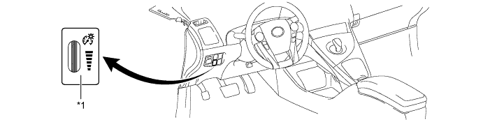
Light Control Rheostat
The brightness of the instrument panel can be adjusted when the taillights are turned on.
The nighttime brightness level of the combination meter can be adjusted between 2.08% and 16.5% of the daytime brightness level of 100%, by using a dial-type switch. The indicator lights on the combination meter can be turned off* by further decreasing the brightness level.
*: Without shift indicator

| *1 | Light Control Rheostat | - | - |
| CONSTRUCTION |
Combination Meter
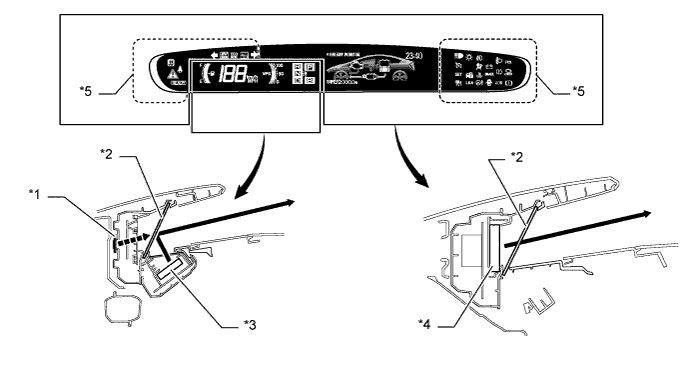
A reflective display method is used to display the speedometer, fuel gauge, instantaneous fuel consumption and shift position. Using the vacuum fluorescent display (VFD), the light emitted by the vacuum fluorescent display panel is reflected in the reflective glass, allowing a virtual image to be visible to the driver's eyes.
Light emitted in the display area is transmitted through the reflective glass, allowing the warning lights, indicator lights and information on the multi-information display to be visible to the driver's eyes.

| *1 | Virtual Image | *2 | Reflective Glass |
| *3 | Vacuum Fluorescent Display | *4 | Vacuum Fluorescent Display or LED Indicator Display |
| *5 | LED Indicator Display | - | - |
Touch Tracer Display
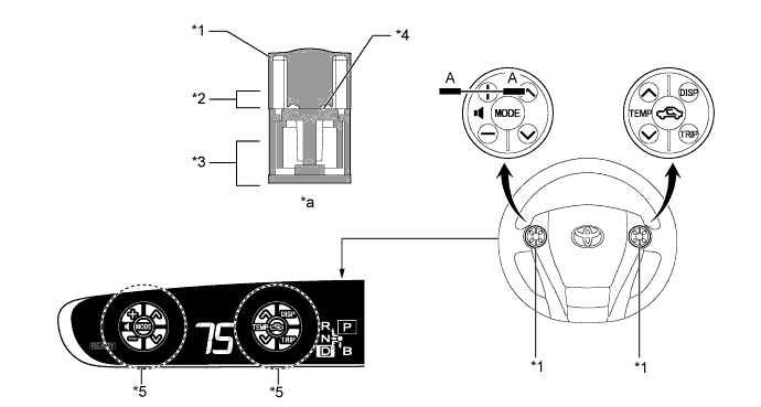
A touch sensor is provided on the following frequently used switches such as the multi-information display mode switch, TRIP/ODO mode switch, audio and air conditioning switches. The touch tracer display is displayed when any of the switches is touched by the driver's finger, and the switch is activated when pressed.
| Steering Pad Switch Assembly | Touch sensor | |
| Audio System | Volume Switch (+) | X |
| Volume Switch (-) | X | |
| Mode Switch | X | |
| Seek Switch (Up) | X | |
| Seek Switch (Down) | X | |
| Multi-information display | TRIP/ODO Mode Switch | X |
| Display Mode Switch | X | |
| Air Conditioning System | Air Inlet Control Switch | X |
| Temp Switch (Up) | X | |
| Temp Switch (Down) | X | |
| Bluetooth Hands-free System | Voice Switch | - |
| On Hook Switch | - | |
| Off Hook Switch | - | |
| Dynamic Radar Cruise Control System | Distance Control Switch | - |
| Lane-keeping Assist System | LKA Main Switch | - |

| *1 | Steering Pad Switch | *2 | Touch Switch Area |
| *3 | Function Switch Area | *4 | Touch Sensor |
| *5 | Touch Tracer Display | - | - |
| *a | A-A Cross Section | - | - |
Headup Display
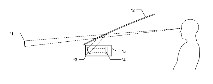
The Headup display projects the image from the dot Vacuum Fluorescent Display (VFD), built into the Headup display unit (combination meter mirror ECU), in a position approximately 2 m (6.6 ft) forward of the driver using a concave mirror and the windshield, in order to support the driver with various information.
By changing the angle of the concave mirror, the position of the image displayed can be adjusted.

| *1 | Headup Display image | *2 | Windshield Glass |
| *3 | Concave mirror | *4 | Dot VFD |
| *5 | Headup Display Unit (Combination Meter Mirror ECU) | - | - |
Windshield Glass for Headup Display
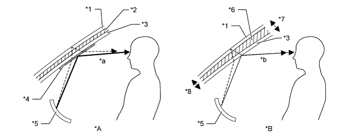
Windshield glass without a combiner treatment is used for the Headup display.
This glass has a wedge-shaped inner film. This film, with its varying thickness, is located between the outer and inner layers of glass.
The light that strikes the glass is reflected by the inner surface of the inner glass, and also by the inner side of the outer surface of outer layer of glass. With a conventional windshield, the light reflected from these 2 surfaces diverges due to the thickness of the glass, resulting in a double image.
The film uses its wedge shape to eliminate the reflection angle difference between the outer glass and inner glass. This recombines the reflected light and eliminates the double image.
Thus, the reflected light from the Headup display unit is recognized by the driver as a single display image.

| *A | Windshield Glass with Normal Film | *B | Windshield Glass with Wedge-shaped Film |
| *1 | Outer Glass | *2 | Uniform Thickness Film |
| *3 | Inner Glass | *4 | Combiner |
| *5 | Concave Mirror | *6 | Wedge-shaped Film |
| *7 | Thick | *8 | Thin |
| *a | The combiner makes the light reflected by the inner glass brighter, however, a double image is caused by a divergence of the reflected light. | *b | Reflected light is recombined and a double image is prevented. |
| OPERATION |
Multi-information Display Mode Switch
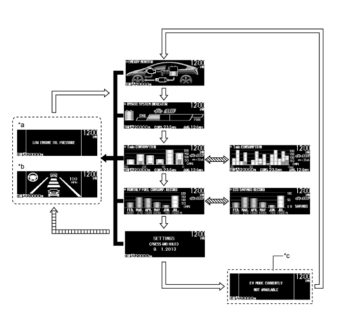
When the customize setting is turned on, the multi-information display changes in the order below each time the multi-information display mode switch is pressed.

| *a | Warning, Caution or Advisory Message | *b | Dynamic Radar Cruise Control System, Pre-collision System and Lane-keeping Assist System are displayed. |
| *c | When advisory conditions are not solved. | - | - |
![]() | Multi-information Display Mode Switch is Pressed Briefly. | ![]() | When warning message, dynamic radar cruise control system, pre-collision system and lane-keeping assist system display request signals are received. |
![]() | Multi-information Display Mode Switch is Pressed and Held. | ![]() | If warning or caution display conditions are still met after returning to the normal information display using the multi-information display mode switch. |
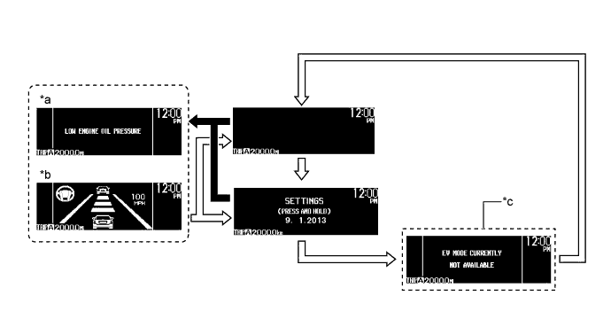
When the customize setting is turned off, the multi-information display changes in the order below each time the multi-information display mode switch is pressed.

| *a | Warning, Caution or Advisory Message | *b | Dynamic Radar Cruise Control System, Pre-collision System and Lane-keeping Assist System are displayed. |
| *c | When advisory conditions are not solved. | - | - |
![]() | Multi-information Display Mode Switch is Pressed Briefly. | ![]() | When warning message, dynamic radar cruise control system, pre-collision system and lane-keeping assist system display request signals are received. |
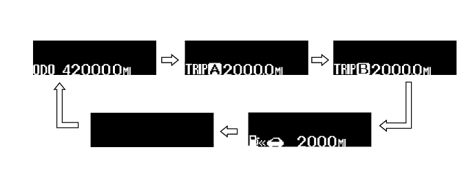
TRIP/ODO Mode Switch
The indication on the trip counter changes in the order below each time the TRIP/ODO mode switch is pressed.

| *1 | TRIP/ODO Mode Switch | *2 | Multi-information Display Mode Switch |
![]() | TRIP/ODO Mode Switch is Pressed Briefly. | - | - |
The trip meter can be reset when the TRIP/ODO mode switch is pressed and held while the trip A or trip B screen is being displayed.
The highest fuel consumption can be reset when the TRIP/ODO mode switch is pressed and held while the trip A or trip B fuel consumption history screen is being displayed.
All the fuel consumption history is reset when the multi-information display mode switch is pressed and held while the fuel consumption graph screen is being displayed.
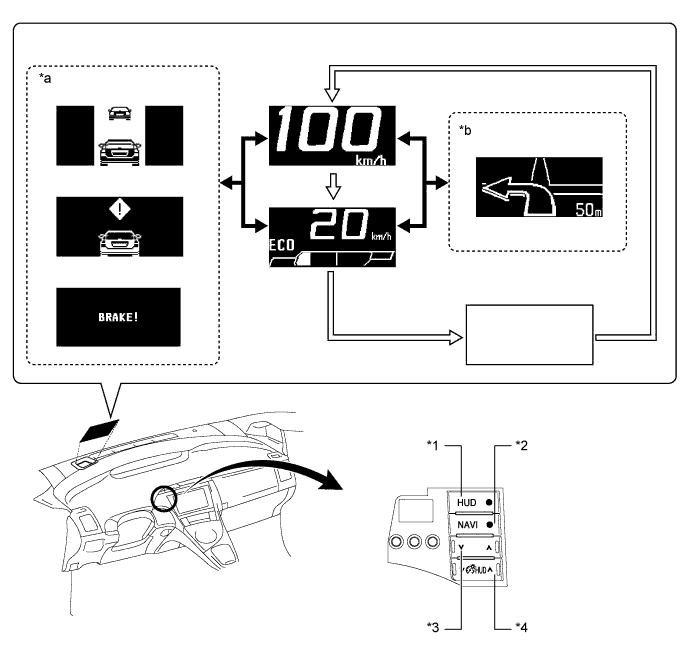
Headup Display Satellite Switch
The headup display changes in the order below by pressing the headup display satellite switch.

| *1 | HUD Main Switch | *2 | NAVI Switch |
| *3 | Headup Display Position Adjustment Switch | *4 | Headup Display Luminance Adjustment Switch |
| *a | Dynamic Radar Cruise Control System, Pre-collision System Warning Indicators are displayed. | *b | Turn-by-turn Navigation Display |
![]() | Headup Display Main Switch is Pressed Briefly. | ![]() | When dynamic radar cruise control system, pre-collision system and turn-by-turn navigation display signals are received. |