DTC P0AA6-526 Hybrid Battery Voltage System Isolation Fault |
DTC P0AA6-611 Hybrid Battery Voltage System Isolation Fault |
DTC P0AA6-612 Hybrid Battery Voltage System Isolation Fault |
DTC P0AA6-613 Hybrid Battery Voltage System Isolation Fault |
DTC P0AA6-614 Hybrid Battery Voltage System Isolation Fault |
| DTC No. | INF Code | DTC Detection Condition | Trouble Area |
| P0AA6 | 526(*1) | Insulation resistance between the high-voltage circuit and the body has decreased.*2 (1 trip detection logic) |
|
| P0AA6 | 611 | Insulation resistance of the compressor with motor assembly or air conditioning inverter has decreased.*3 (1 trip detection logic) | Compressor with motor assembly |
| P0AA6 | 612 | Insulation resistance of the HV battery, battery smart unit, SMR or SMRG has decreased.*3 (1 trip detection logic) |
|
| P0AA6 | 613 | Insulation resistance of the hybrid vehicle transaxle assembly or inverter for generator (MG1) and motor (MG2) has decreased.*3 (1 trip detection logic) |
|
| P0AA6 | 614 | Insulation resistance of the inverter for generator (MG1) and motor (MG2), A/C inverter, SMR, SMRG or frame wire has decreased.*3 (1 trip detection logic) |
|
| DTC No. | Data List |
| P0AA6-526 |
|
| P0AA6-611 | |
| P0AA6-612 | |
| P0AA6-613 | |
| P0AA6-614 |
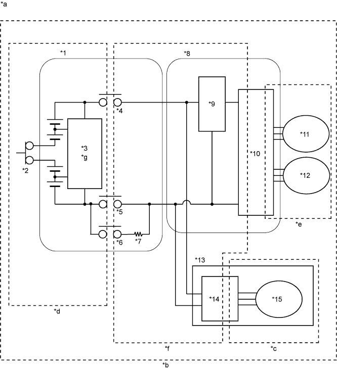
| *1 | HV Battery | *2 | Service Plug Grip |
| *3 | Battery Smart Unit | *4 | SMRB |
| *5 | SMRG | *6 | SMRP |
| *7 | System Main Resistor | *8 | Inverter with Converter Assembly |
| *9 | Boost Converter | *10 | Inverter |
| *11 | MG1 | *12 | MG2 |
| *13 | Compressor with Motor Assembly | *14 | A/C Inverter |
| *15 | A/C Motor | - | - |
| *a | High-voltage Areas | *b | INF Code 526 Vehicle Insulation Resistance Reduction Area |
| *c | INF Code 611 Air Conditioning Area | *d | INF Code 612 HV Battery Area |
| *e | INF Code 613 Transaxle Area | *f | INF Code 614 High Voltage Direct Current Area |
| *g | Insulation Monitoring Circuit (Equipped with insulation malfunction detection circuit) | - | - |
| SHORT WAVE HIGHEST VALUE |
"Short Wave Highest Val" indicates a decrease in insulation resistance and decreases the value as the insulation resistance decreases. In some cases, "Short Wave Highest Val" may decrease even though the insulation resistance of the vehicle is normal, therefore avoid checking "Short Wave Highest Val" when any of the following conditions exist.
When "Short Wave Highest Val" is approximately 0 V, insulation resistance is close to 0 Ω. In this case, damage to a high-voltage cable or hybrid component (high-voltage), or a short to the body due to intrusion of foreign matter such as metal particles can be suspected.
| RELATED FREEZE FRAME DATA |
| Freeze Frame Data | Diagnostic Note |
| Short Wave Highest Val | Indicates that the insulation resistance has decreased. |
| During boosting (when "Boost Ratio" is not 0%), or when "VL-Voltage before Boosting", "VH-Voltage after Boosting" or "Power Resource VB" is varying, "Short Wave Highest Val" may decrease even though the insulation resistance is normal. |
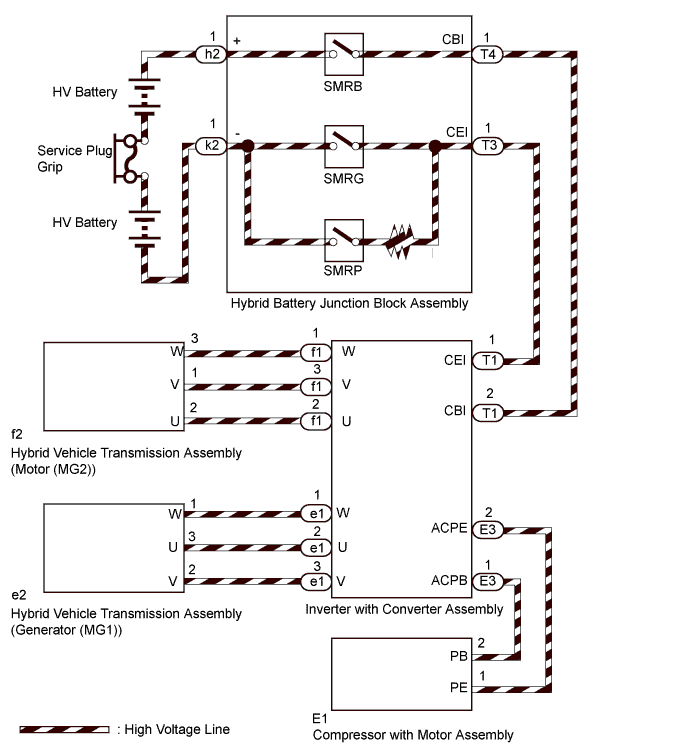
| When "SMRP Status", "SMRB Status" and "SMRG Status" are all OFF, the insulation malfunction detection circuit detects a decrease in insulation resistance in the HV battery area ((*d) in the wiring diagram).
|
| MG2 Gate Status | When "MG2 Gate Status" is ON, the insulation malfunction detection circuit cannot detect a decrease in insulation resistance in the motor system AC (alternating current) section (motor (MG2) side of (*e) in the wiring diagram). The motor system AC (alternating current) section includes the motor (MG2) in the hybrid vehicle transaxle assembly, motor cables and the AC (alternating current) section of the motor drive circuit in the inverter with converter assembly. |
| MG1 Gate Status | When "MG1 Gate Status" is ON, the insulation malfunction detection circuit cannot detect a decrease in insulation resistance in the generator system AC (alternating current) section (generator (MG1) side of (*e) in the wiring diagram). The generator system AC (alternating current) section includes the generator (MG1) in the hybrid vehicle transaxle assembly, generator cables and the AC (alternating current) section of the generator drive circuit in the inverter with converter assembly. |
| A/C Consumption Pwr | When the air conditioning system is off (air conditioning system power consumption is 0 W), the insulation malfunction detection circuit cannot detect a decrease in insulation resistance in the compressor with motor assembly AC (alternating current) section ((*c) in the wiring diagram). The compressor with motor assembly AC (alternating current) section includes the air conditioning motor, wiring between the air conditioning motor and air conditioning inverter, and the AC (alternating current) section of the air conditioning motor drive circuit in the air conditioning inverter. With the vehicle stopped, turn on/off the air conditioning system and observe "Short Wave Highest Val" to use as a diagnosis reference. |
| Item | Diagnostic Note |
| Vehicle Spd | - |
| Accel Pedal Pos #1 | - |
| Engine Revolution | - |
| Shift Sensor Shift Pos | - |
| Master Cylinder Ctrl Trq | - |
| Engine Coolant Temp | - |
| Item | Diagnostic Note |
| Motor Temp No1 | If any liquid leaks into the ATF, insulation resistance may decrease only when the temperature is high. The motor temperature is likely to increase if the motor speed is low and output torque is high such as when cruising uphill slowly or accelerating from a low speed. |
| Motor Temp No2 | If any liquid leaks into the ATF, insulation resistance may decrease only when the temperature is high. The generator temperature is likely to increase under repeat acceleration and deceleration while the vehicle is driven in the mid speed range (37 to 50 mph (60 to 80 km/h)). |
| Item | Diagnostic Note |
| Driving Condition (acceleration, deceleration, turning, etc.) | Changes in the insulation of the parts with insufficient insulation due to changes in G force or vibration is suspected. |
| Road Condition (unpaved, etc.) | |
| Weather (rain, snow, etc.) | Water intrusion is suspected |
| Washing the vehicle (Whether the malfunction occurred after washing the vehicle?) |
| CONFIRMATION AFTER REPLACING PARTS |
After the repair, clear the DTCs and perform the following procedure to check that DTCs are not output. (Do not turn the power switch off (READY off) during this inspection.)
Apply the parking brake and secure the wheels using chocks.
When the vehicle is stationary, turn the power switch on (READY) with park (P) selected and wait for 60 seconds or more.
Turn the air conditioning system on (MAX COLD, blower speed HI).
While depressing the brake pedal without depressing the accelerator pedal, move the shift lever to D and wait for 5 minutes.
Drive the vehicle for approximately 5 minutes referring to the following freeze frame data items: "Vehicle Spd", "Shift Sensor Shift Pos", "Accel Pedal Pos #1", "Engine Revolution", "Engine Coolant Temp" and "Master Cylinder Ctrl Trq"
(If the freeze frame data item "Vehicle Spd" is 6 mph (10 km/h) or less, drive the vehicle at 6 mph (10 km/h) or more.).
Wait for 1 minute or more with the vehicle stopped, the power switch on (READY), the shift lever in P and the air conditioning system on (Lo/COOL MAX, blower speed HI), then turn the power switch off and wait for 1 minute or more. (*)
| 1.CHECK DTC OUTPUT (HV) |
Connect the Techstream to the DLC3.
Turn the power switch on (IG).
Enter the following menus: Powertrain / Hybrid Control / Trouble Codes.
Check if DTCs are output.
| Result | Proceed to |
| P0AA6 only is output. | A |
| P0AA6 and P0A1D (power management control ECU malfunction) are output. | B |
| P0AA6 and P0AA7 (malfunction in the battery smart unit) are output. | C |
| P0AA6 and P0A1F (battery ECU malfunction) are output. | D |
Turn the power switch off.
|
| ||||
|
| ||||
|
| ||||
| A | |
 |
| 2.CHECK INFORMATION CODE |
Connect the Techstream to the DLC3.
Turn the power switch on (IG).
Enter the following menus: Powertrain / Hybrid Control / Trouble Codes.
Access the freeze frame data of DTC P0AA6 and read the INF code.
| Result | Proceed to |
| 526 (decrease in the insulation resistance of the high-voltage circuit) only is output. | A |
| 526 and 611 (decrease in the insulation resistance of the air conditioning area) are output. | Refer to the troubleshooting procedures for P0AA6-611 (Heater and air conditioning system) (Click here) |
| 526 and 612 (decrease in the insulation resistance of the battery area) are output. | B |
| 526 and 613 (decrease in the insulation resistance of the transaxle area) are output. | C |
| 526 and 614 (decrease in the insulation resistance of the high-voltage DC area) are output. | D |
Turn the power switch off.
|
| ||||
|
| ||||
|
| ||||
| A | |
|
| 3.CHECK HYBRID VEHICLE TRANSAXLE ASSEMBLY (MOTOR CABLE) |
Turn the power switch off.
Check that the service plug grip is not installed.
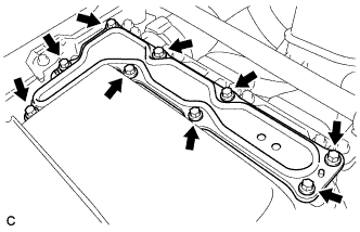 |
Remove the inverter terminal cover from the inverter with converter assembly.
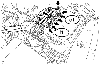 |
Disconnect the motor cable e1 and generator cable f1 from the inverter with converter assembly.
Connect the cable to the negative (-) auxiliary battery terminal.
Turn the power switch on (IG).
With the neutral (N) selected and lift up the vehicle.
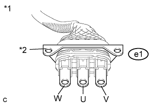 |
Using a megohmmeter set to 500 V, measure the resistance according to the value(s) in the table below while rotating the front wheels 2 revolutions in the same direction simultaneously.
| Tester Connection | Switch Condition | Specified Condition |
| e1-3 (V) - Body ground and shielded wire ground | Power switch off | 100 MΩ or higher |
| e1-2 (U) - Body ground and shielded wire ground | Power switch off | 100 MΩ or higher |
| e1-1 (W) - Body ground and shielded wire ground | Power switch off | 100 MΩ or higher |
| *1 | Motor Cable |
| *2 | Shielded Wire Ground |
Lower the vehicle and push the P position switch.
Turn the power switch off.
Disconnect the cable from the negative (-) auxiliary battery terminal.
|
| ||||
| OK | |
|
| 4.CHECK HYBRID VEHICLE TRANSAXLE ASSEMBLY (GENERATOR CABLE) |
Check that the service plug grip is not installed.
Connect the cable to the negative (-) auxiliary battery terminal.
Turn the power switch on (IG).
With the neutral (N) selected and lift up the vehicle.
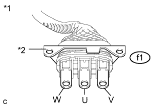 |
Using a megohmmeter set to 500 V, measure the resistance according to the value(s) in the table below while rotating the front wheels 2 revolutions in the same direction simultaneously.
| Tester Connection | Switch Condition | Specified Condition |
| f1-3 (V) - Body ground and shielded wire ground | Power switch off | 100 MΩ or higher |
| f1-2 (U) - Body ground and shielded wire ground | Power switch off | 100 MΩ or higher |
| f1-1 (W) - Body ground and shielded wire ground | Power switch off | 100 MΩ or higher |
| *1 | Generator Cable |
| *2 | Shielded Wire Ground |
Lower the vehicle and push the P position switch.
Turn the power switch off.
Disconnect the cable from the negative (-) auxiliary battery terminal.
|
| ||||
| OK | |
|
| 5.CHECK NO. 2 ENGINE WIRE |
Check that the service plug grip is not installed.
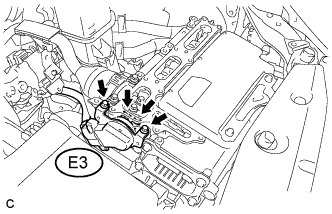 |
Disconnect the No. 2 engine wire (air conditioning harness) E3 from the inverter with converter assembly.
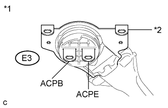 |
Using a megohmmeter set to 500 V, measure the resistance according to the value(s) in the table below.
| Tester Connection | Switch Condition | Specified Condition |
| E3-1 (ACPB) - Body ground and shield ground | Power switch off | 3 MΩ or higher |
| E3-2 (ACPE) - Body ground and shield ground | Power switch off | 3 MΩ or higher |
| *1 | No. 2 Engine Wire (Air Conditioning Harness) |
| *2 | Shield Ground |
|
| ||||
| OK | |
|
| 6.CHECK INVERTER WITH CONVERTER ASSEMBLY |
Check that the service plug grip is not installed.
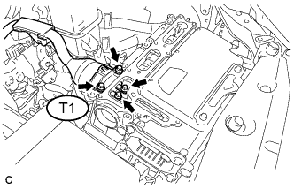 |
Disconnect the frame wire T1 from the inverter with converter assembly.
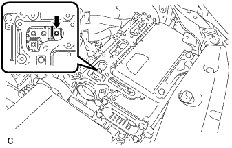 |
Using a megohmmeter set to 500 V, measure the resistance according to the value(s) in the table below.
| Tester Connection | Switch Condition | Specified Condition |
| High voltage terminal - Body ground | Power switch off | 1 MΩ or higher |
|
| ||||
| OK | |
|
| 7.CHECK FRAME WIRE |
Check that the service plug grip is not installed.
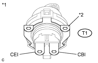 |
Using a megohmmeter set to 500 V, measure the resistance according to the value(s) in the table below.
| Tester Connection | Switch Condition | Specified Condition |
| T1-1 (CEI) - Body ground and shield ground | Power switch off | 10 MΩ or higher |
| T1-2 (CBI) - Body ground and shield ground | Power switch off | 10 MΩ or higher |
| *1 | Frame Wire |
| *2 | Shield Ground |
|
| ||||
| OK | |
|
| 8.CHECK HV BATTERY AREA |
Turn the power switch off.
Check that the service plug grip is not installed.
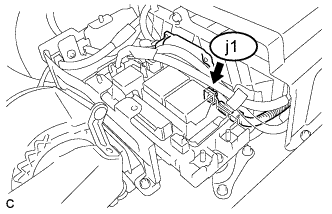 |
Disconnect connector j1 from the battery smart unit
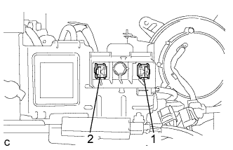 |
Using a megohmmeter set to 500 V, measure the resistance according to the value(s) in the table below.
| Tester Connection | Switch Condition | Specified Condition |
| 1 - Body ground | Power switch off | 10 MΩ or higher |
| 2 - Body ground | Power switch off | 10 MΩ or higher |
|
| ||||
| OK | |
|
| 9.REPLACE BATTERY SMART UNIT |
Replace the battery smart unit (Click here).
| NEXT | ||
 | ||
| ||
| 10.CHECK INVERTER WITH CONVERTER ASSEMBLY |
Turn the power switch off.
Check that the service plug grip is not installed.
|
Remove the inverter terminal cover from the inverter with converter assembly.
|
Disconnect the motor cable e1 and generator cable f1 from the inverter with converter assembly.
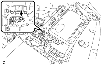 |
Using a megohmmeter set to 500 V, measure the resistance according to the value(s) in the table below.
| Tester Connection | Switch Condition | Specified Condition |
| High voltage terminal - Body ground | Power switch off | 1 MΩ or higher |
| Result | Proceed to |
| NG | A |
| OK | B |
|
| ||||
| A | |
|
| 11.REPLACE INVERTER WITH CONVERTER ASSEMBLY |
Replace the inverter with converter assembly (Click here).
| NEXT | ||
| ||
| ||
| 12.CHECK HYBRID VEHICLE TRANSAXLE ASSEMBLY (MOTOR CABLE) |
Turn the power switch off.
Check that the service plug grip is not installed.
|
Remove the inverter terminal cover from the inverter with converter assembly.
|
Disconnect the motor cable e1 and generator cable f1 from the inverter with converter assembly.
Connect the cable to the negative (-) auxiliary battery terminal.
Turn the power switch on (IG).
With the neutral (N) selected and lift up the vehicle.
|
Using a megohmmeter set to 500 V, measure the resistance according to the value(s) in the table below while rotating the front wheels 2 revolutions in the same direction simultaneously.
| Tester Connection | Switch Condition | Specified Condition |
| e1-3 (V) - Body ground and shielded wire ground | Power switch off | 100 MΩ or higher |
| e1-2 (U) - Body ground and shielded wire ground | Power switch off | 100 MΩ or higher |
| e1-1 (W) - Body ground and shielded wire ground | Power switch off | 100 MΩ or higher |
| *1 | Motor Cable |
| *2 | Shielded Wire Ground |
Lower the vehicle and push the P position switch.
Turn the power switch off.
Disconnect the cable from the negative (-) auxiliary battery terminal.
|
| ||||
| OK | |
|
| 13.CHECK HYBRID VEHICLE TRANSAXLE ASSEMBLY (GENERATOR CABLE) |
Check that the service plug grip is not installed.
Connect the cable to the negative (-) auxiliary battery terminal.
Turn the power switch on (IG).
With the neutral (N) selected and lift up the vehicle.
|
Using a megohmmeter set to 500 V, measure the resistance according to the value(s) in the table below while rotating the front wheels 2 revolutions in the same direction simultaneously.
| Tester Connection | Switch Condition | Specified Condition |
| f1-3 (V) - Body ground and shielded wire ground | Power switch off | 100 MΩ or higher |
| f1-2 (U) - Body ground and shielded wire ground | Power switch off | 100 MΩ or higher |
| f1-1 (W) - Body ground and shielded wire ground | Power switch off | 100 MΩ or higher |
| *1 | Generator Cable |
| *2 | Shielded Wire Ground |
Lower the vehicle and push the P position switch.
Turn the power switch off.
Disconnect the cable from the negative (-) auxiliary battery terminal.
|
| ||||
| OK | |
|
| 14.CHECK HIGH VOLTAGE DIRECT CURRENT AREA |
Turn the power switch off.
Check that the service plug grip is not installed.
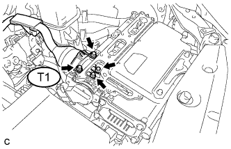 |
Disconnect the frame wire T1 from the inverter with converter assembly.
|
Using a megohmmeter set to 500 V, measure the resistance according to the value(s) in the table below.
| Tester Connection | Switch Condition | Specified Condition |
| T1-1 (CEI) - Body ground and shield ground | Power switch off | 10 MΩ or higher |
| T1-2 (CBI) - Body ground and shield ground | Power switch off | 10 MΩ or higher |
| *1 | Frame Wire |
| *2 | Shield Ground |
|
| ||||
| OK | |
|
| 15.CHECK NO. 2 ENGINE WIRE |
Check that the service plug grip is not installed.
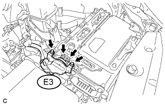 |
Disconnect the No. 2 engine wire (air conditioning harness) E3 from the inverter with converter assembly.
|
Using a megohmmeter set to 500 V, measure the resistance according to the value(s) in the table below.
| Tester Connection | Switch Condition | Specified Condition |
| E3-1 (ACPB) - Body ground and shield ground | Power switch off | 3 MΩ or higher |
| E3-2 (ACPE) - Body ground and shield ground | Power switch off | 3 MΩ or higher |
| *1 | No. 2 Engine Wire (Air Conditioning Harness) |
| *2 | Shield Ground |
|
| ||||
| OK | |
|
| 16.REPLACE INVERTER WITH CONVERTER ASSEMBLY |
Replace the inverter with converter assembly (Click here).
| NEXT | ||
| ||
| ||
| 17.CHECK NO. 2 ENGINE WIRE |
Check that the service plug grip is not installed.
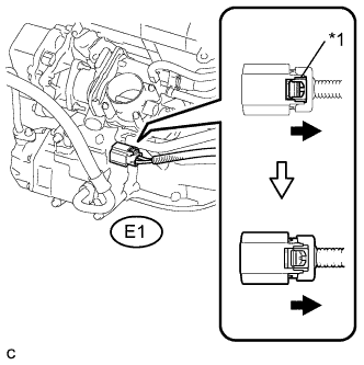 |
Disconnect the No. 2 engine wire (air conditioning harness) E1 from the compressor with motor assembly.
| *1 | Green Lock |
|
Using a megohmmeter set to 500 V, measure the resistance according to the value(s) in the table below.
| Tester Connection | Switch Condition | Specified Condition |
| E3-1 (ACPB) - Body ground and shield ground | Power switch off | 10 MΩ or higher |
| E3-2 (ACPE) - Body ground and shield ground | Power switch off | 10 MΩ or higher |
| *1 | No. 2 Engine Wire (Air Conditioning Harness) |
| *2 | Shield Ground |
|
| ||||
| OK | |
|
| Go to step 32 |
| 18.CHECK FRAME WIRE |
Check that the service plug grip is not installed.
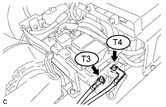 |
Disconnect the frame wire T4 and T3 from the hybrid battery junction block assembly.
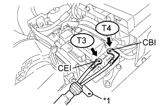 |
Using a megohmmeter set to 500 V, measure the resistance according to the value(s) in the table below.
| Tester Connection | Switch Condition | Specified Condition |
| T4-1 (CBI) - Body ground and shield ground | Power switch off | 10 MΩ or higher |
| T3-1 (CEI) - Body ground and shield ground | Power switch off | 10 MΩ or higher |
| *1 | Shield Ground |
|
| ||||
| OK | |
|
| 19.REPLACE HYBRID BATTERY JUNCTION BLOCK ASSEMBLY |
Replace the hybrid battery junction block assembly (Click here).
| NEXT | ||
| ||
| ||
| 20.CHECK HYBRID BATTERY JUNCTION BLOCK ASSEMBLY |
Check that the service plug grip is not installed.
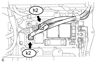 |
Disconnect the high voltage cable connector of the HV battery h2 and k2 from the hybrid battery junction block assembly.
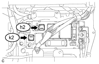 |
Using a megohmmeter set to 500 V, measure the resistance according to the value(s) in the table below.
| Tester Connection | Switch Condition | Specified Condition |
| k2-1 (-) - Hybrid Battery Carrier Panel | Power switch off | 10 MΩ or higher |
| h2-1 (+) - Hybrid Battery Carrier Panel | Power switch off | 10 MΩ or higher |
|
| ||||
| OK | |
|
| 21.REPLACE HV BATTERY |
Replace the HV battery (Click here).
| NEXT | ||
| ||
| ||
| 22.CHECK MOTOR CABLE |
Turn the power switch off.
Check that the service plug grip is not installed.
Disconnect the motor cable from the hybrid vehicle transaxle assembly (Click here).
|
Using a megohmmeter set to 500 V, measure the resistance according to the value(s) in the table below.
| Tester Connection | Switch Condition | Specified Condition |
| e1-3 (V) - Body ground and shield ground | Power switch off | 100 MΩ or higher |
| e1-2 (U) - Body ground and shield ground | Power switch off | 100 MΩ or higher |
| e1-1 (W) - Body ground and shield ground | Power switch off | 100 MΩ or higher |
| *1 | Motor Cable |
| *2 | Shield Ground |
|
| ||||
| OK | |
|
| Go to step 33 |
| 23.CHECK GENERATOR CABLE |
Check that the service plug grip is not installed.
Disconnect the generator cable from the hybrid vehicle transaxle assembly (Click here).
|
Using a megohmmeter set to 500 V, measure the resistance according to the value(s) in the table below.
| Tester Connection | Switch Condition | Specified Condition |
| f1-3 (V) - Body ground and shield ground | Power switch off | 100 MΩ or higher |
| f1-2 (U) - Body ground and shield ground | Power switch off | 100 MΩ or higher |
| f1-1 (W) - Body ground and shield ground | Power switch off | 100 MΩ or higher |
| *1 | Generator Cable |
| *2 | Shield Ground |
|
| ||||
| OK | |
|
| Go to step 33 |
| 24.CHECK MOTOR CABLE |
Turn the power switch off.
Check that the service plug grip is not installed.
Disconnect the motor cable from the hybrid vehicle transaxle assembly (Click here).
|
Using a megohmmeter set to 500 V, measure the resistance according to the value(s) in the table below.
| Tester Connection | Switch Condition | Specified Condition |
| e1-3 (V) - Body ground and shield ground | Power switch off | 100 MΩ or higher |
| e1-2 (U) - Body ground and shield ground | Power switch off | 100 MΩ or higher |
| e1-1 (W) - Body ground and shield ground | Power switch off | 100 MΩ or higher |
| *1 | Motor Cable |
| *2 | Shield Ground |
|
| ||||
| OK | |
|
| 25.CHECK GENERATOR CABLE |
Check that the service plug grip is not installed.
Disconnect the generator cable from the hybrid vehicle transaxle assembly (Click here).
|
Using a megohmmeter set to 500 V, measure the resistance according to the value(s) in the table below.
| Tester Connection | Switch Condition | Specified Condition |
| f1-3 (V) - Body ground and shield ground | Power switch off | 100 MΩ or higher |
| f1-2 (U) - Body ground and shield ground | Power switch off | 100 MΩ or higher |
| f1-1 (W) - Body ground and shield ground | Power switch off | 100 MΩ or higher |
| *1 | Generator Cable |
| *2 | Shield Ground |
|
| ||||
| OK | |
|
| Go to step 33 |
| 26.REPLACE INVERTER WITH CONVERTER ASSEMBLY |
Replace the inverter with converter assembly (Click here).
| NEXT | ||
| ||
| ||
| 27.REPLACE NO. 2 ENGINE WIRE |
Replace the No. 2 engine wire (Click here).
| NEXT | ||
| ||
| ||
| 28.REPLACE FRAME WIRE |
Replace the frame wire (Click here).
| NEXT | ||
| ||
| ||
| 29.REPLACE HYBRID BATTERY JUNCTION BLOCK ASSEMBLY |
Replace the hybrid battery junction block assembly (Click here).
| NEXT | ||
| ||
| ||
| 30.REPLACE MOTOR CABLE |
Replace the motor cable (Click here).
| NEXT | ||
| ||
| ||
| 31.REPLACE GENERATOR CABLE |
Replace the generator cable (Click here).
| NEXT | ||
| ||
| ||
| 32.GO TO AIR CONDITIONING SYSTEM (P0AA6-611) |
| NEXT | ||
| ||
| ||
| 33.REPLACE HYBRID VEHICLE TRANSAXLE ASSEMBLY |
Replace the hybrid vehicle transaxle assembly (Click here).
| NEXT | ||
| ||
| ||

