 |
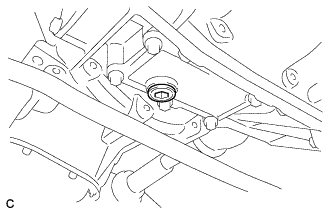
Using a hexagon wrench (10 mm), remove the drain plug indicated in the illustration and drain the coolant.
- CAUTION:
- Use caution when handling coolant immediately after driving or in summer because it may be hot.
COOLANT (for Inverter) > REPLACEMENT |
| 1. REMOVE FRONT SPOILER COVER (for Standard) |
| 2. REMOVE ENGINE UNDER COVER (w/ Cover) |
| 3. DRAIN COOLANT (for Inverter) |
Remove the reserve tank cap.
|
Using a hexagon wrench (10 mm), remove the drain plug indicated in the illustration and drain the coolant.
Install the plug with a new gasket.
| 4. ADD COOLANT (for Inverter) |
| DTC Code | Detection Item |
| P0A01-726 | Motor Electronics Coolant Temperature Sensor Circuit Range / Performance |
| P0A04-725 | Motor Electronics Coolant Temperature Sensor Circuit Intermittent |
| P0A08-264 | DC / DC Converter Status Circuit |
| P0A78-284 | Drive Motor "A" Inverter Performance |
| P0A78-286 | Drive Motor "A" Inverter Performance |
| P0A7A-322 | Generator Inverter Performance |
| P0A7A-324 | Generator Inverter Performance |
| P0A93-346 | Inverter Cooling System Performance |
| P0A94-553 | DC / DC Converter Performance |
| P0A94-557 | DC / DC Converter Performance |
| P0AEE-277 | Motor Inverter Temperature Sensor "A" Circuit Range / Performance |
| P0AF1-276 | Drive Motor Inverter Temperature Sensor "A" Circuit Intermittent / Erratic |
| P0BCD-315 | Generator Inverter Temperature Sensor Circuit Range / Performance |
| P0BD0-314 | Generator Inverter Temperature Sensor Circuit Intermittent / Erratic |
| P0C39-626 | DC / DC Converter Temperature Sensor "A" Range / Performance |
| P0C3C-625 | DC / DC Converter Temperature Sensor "A" Intermittent / Erratic |
| P0C3E-628 | DC / DC Converter Temperature Sensor "B" Range / Performance |
| P0C41-627 | DC / DC Converter Temperature Sensor "B" Intermittent / Erratic |
| P0C73-776 | Motor Electronics Coolant Pump "A" Control Performance |
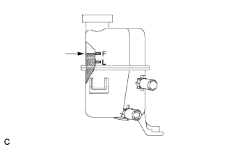 |
Slowly pour coolant into the reserve tank until it reaches the F line.
When using the Techstream:
Connect the Techstream to the DLC3.
Turn the power switch on (IG).
On the Techstream, enter the following menus: Powertrain / Hybrid Control / Active Test / Activate the Water Pump.
Keep the coolant at the F line in the reserve tank to compensate for the drop in coolant level when the air bleeds.
When not using the Techstream:
Turn the power switch on (READY). [*1]
Turn the power switch off and add coolant to the F line because the coolant level drops as the air bleeds. [*2]
Repeat steps [*1] and [*2] until air bleeding from the cooling system is completed.
After the air is completely bled from the cooling system, tighten the reserve tank cap.
|
Add coolant to the F line of the reserve tank.
| 5. INSPECT FOR COOLANT LEAK (for Inverter) |
Remove the reserve tank cap.
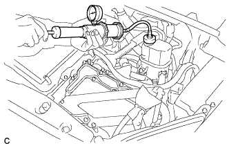 |
Install the radiator cap tester.
Pump the radiator cap tester to 122 kPa (1.2 kgf/ cm2, 17.7 psi), and then check that the pressure does not drop.
Reinstall the reserve tank cap.
| 6. INSTALL ENGINE UNDER COVER (w/ Cover) |
| 7. INSTALL FRONT SPOILER COVER (for Standard) |