Home › Steering › STEERING COLUMN › STEERING COLUMN ASSEMBLY

STEERING COLUMN ASSEMBLY > REASSEMBLY

for Preparation Click here


NOTICE:
  1. When using a vise, do not overtighten it.
  2. Do not drop the power steering motor assembly, strike it with tools or subject it to impacts.
  3. If the power steering motor assembly is subjected to an impact, replace it with a new one.
  4. Do not pull the wire harness of the power steering motor assembly.
  5. Do not allow any moisture to come into contact with the power steering motor assembly.
  6. Do not loosen any bolts not mentioned in the procedure.


1. INSTALL POWER STEERING MOTOR ASSEMBLY (for Brush Type Motor)


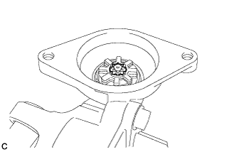
    C248385
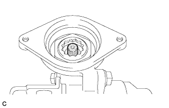
  1. Apply grease to the serrated part of the electric power steering column sub-assembly.

    NOTICE:
    First wipe off the existing grease from the serrated part, and then apply the dedicated grease supplied with a new power steering motor assembly or electric power steering column sub-assembly.
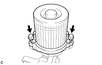
    C248386
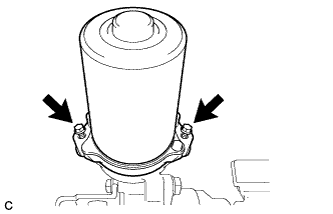
  1. Temporarily install the power steering motor assembly to the electric power steering column sub-assembly with the 2 bolts.

    NOTICE:
    When temporarily installing the 2 bolts to the power steering motor assembly, do not tighten them all the way down.


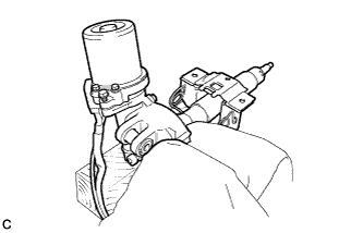
    C248387
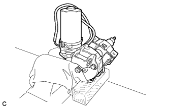
  1. Secure the steering column assembly in a vice using aluminum plates, wooden block and a piece of cloth.

    NOTICE:
    1. Do not overtighten the vice, as the steering column assembly may become deformed.
    2. Secure the steering column assembly so that power steering motor assembly is directly upright.
    3. Support the steering column assembly with a wooden block or similar item to ensure that it does not fall.


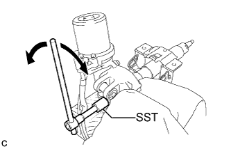
    C248388E01
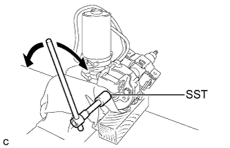
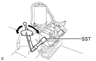
  1. Using SST, turn the steering main shaft once 180 degrees to the left and then 180 degrees to the right at a speed of 60 rpm, and repeat 2 to 3 times to adjust the axis centering of the power steering motor assembly.

    SST
    09616-00011  

  1. Remove the steering column assembly from the vice.

  1. Tighten the 2 bolts.

    Torque:
    19 N*m{ 189 kgf*cm , 14 ft.*lbf }


    C248387
  1. Secure the steering column assembly in a vice using aluminum plates, wooden block and a piece of cloth.

    NOTICE:
    1. Do not overtighten the vice, as the steering column assembly may become deformed.
    2. Support the steering column assembly with a wooden block or similar item to ensure that it does not fall.


    C248389E01
  1. Measure the turning torque of the steering main shaft using SST.

    SST
    09616-00011  

    Torque:
    Turning torque:
    1.1 N*m{ 11 kgf*cm , 10 in.*lbf } or less

    NOTICE:
    Ensure that there is no abnormal resistance during rotation.

    If the torque is not as specified, readjust the axis centering of the power steering motor assembly.


    C248395E01
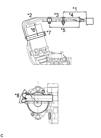
  1. Install 2 new clamps and tape to the wire harness as shown in the illustration.
    Text in Illustration 
    *1
    225 to 245 mm (8.86 to 9.64 in.)
    *2
    115 to 135 mm (4.53 to 5.31 in.)
    *3
    260 mm (10.2 in.)
    *4
    80 to 100 mm (3.15 to 3.93 in.)
    *5
    340 to 360 mm (13.4 to 14.1 in.)
    *6
    10 to 30 mm (0.394 to 1.18 in.)
    *7
    19 mm (0.75 in.)
    *8
    45° or less

    NOTICE:
    1. Secure the wire harness to the power steering motor assembly within the range indicated by *8
    2. Wrap the tape more than 2 times.
    3. As heat from the power steering motor assembly may generate smoke, use heat resistant tape (resistant to 100°C (212°F) or more).


2. INSTALL POWER STEERING MOTOR ASSEMBLY (for Brushless Type Motor)


    C221492
  1. Install a new electric power steering motor shaft damper to the electric power steering column sub-assembly.


    C221491
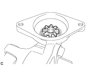
  1. Install a new electric power steering motor shaft spacer to the electric power steering column sub-assembly.


    C221493
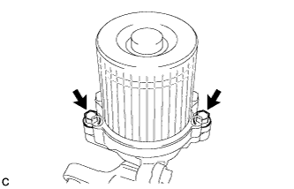
  1. Temporarily install the power steering motor assembly to the electric power steering column sub-assembly with the 2 bolts.

    NOTICE:
    When temporarily installing the 2 bolts to the power steering motor assembly, do not tighten them all the way down.


    C221494
  1. Secure the steering column assembly in a vice using aluminum plates and a piece of cloth.

    NOTICE:
    1. Do not overtighten the vice, as the steering column assembly may become deformed.
    2. Secure the power steering motor assembly so that it is directly upright.
    3. Support the steering column assembly with a wooden block or similar item to ensure that it does not fall.


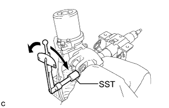
    C221495E01
  1. Using SST, turn the steering main shaft once 180 degrees to the left and then 180 degrees to the right at a speed of 60 rpm, and repeat 2 to 3 times to adjust the axis centering of the power steering motor assembly.

    SST
    09616-00011  

  1. Remove the steering column assembly from the vice.


    C221496
  1. Tighten the 2 bolts.

    Torque:
    19 N*m{ 189 kgf*cm , 14 ft.*lbf }


    C221494
  1. Secure the steering column assembly in a vice using aluminum plates and a piece of cloth.

    NOTICE:
    1. Do not overtighten the vice, as the steering column assembly may become deformed.
    2. Support the steering column assembly with a wooden block or similar item to ensure that it does not fall.


    C221497E01
  1. Measure the turning torque of the steering main shaft using SST.

    SST
    09616-00011  

    Torque:
    Turning torque:
    0.9 to 1.5 N*m{ 10 to 15 kgf*cm , 8 to 12 in.*lbf }

    NOTICE:
    Ensure that there is no abnormal resistance during rotation.

    If the torque is not as specified, readjust the axis centering of the power steering motor assembly.


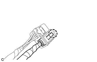
    C220815
  1. Engage the claw to install the torque sensor harness connector.


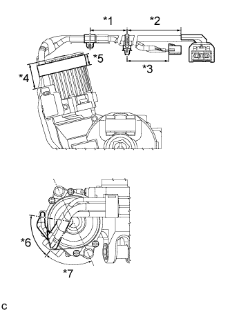
    C248396E01
  1. Install 2 new clamps and tape to the wire harness as shown in the illustration.
    Text in Illustration 
    *1
    175 to 195 mm (6.89 to 7.67 in.)
    *2
    230 to 250 mm (9.06 to 9.84 in.)
    *3
    220 to 240 mm (8.67 to 9.44 in.)
    *4
    Wrap the Tape In This Area
    *5
    19 mm (0.75 in.)
    *6
    59°
    *7
    65°

    NOTICE:
    1. Secure the wire harness to the power steering motor assembly within the range indicated by *6
    2. Wrap the tape more than 2 times.
    3. As heat from the power steering motor assembly may generate smoke, use heat resistant tape (resistant to 100°C (212°F) or more).