Home › Engine / Hybrid System › HYBRID / BATTERY CONTROL › HYBRID CONTROL SYSTEM

DTC    P0C76-523    Hybrid Battery System Discharge Time Too Long

for Preparation Click here


DESCRIPTION

Refer to the description for DTC P0A78-266 .

DTC No.
INF Code
DTC Detection Condition
Trouble Area
P0C76
523
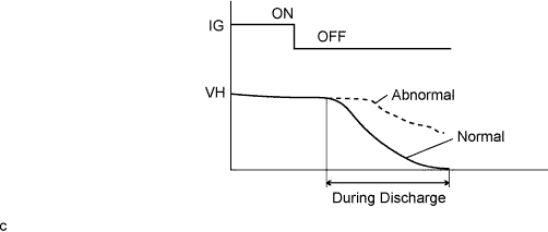
The inverter voltage (VH) does not drop during discharge.
(Discharge: Offsetting of the residual voltage pressure in the high-voltage side after power switch is turned off)
(1 trip detection logic)
Inverter with converter assembly

HINT:
When the power switch is turned from on (READY) to off, the MG ECU discharges voltage stored in the inverter by allowing current to flow to motor (MG2) without generating torque. When the vehicle is normal, VH voltage becomes approximately 0 V after discharging. If VH voltage exceeds a specified value, this DTC is stored.


A111758E02


Related Data List 
DTC No.
Data List
P0C76-523
VL-Voltage before Boosting
The following items can be helpful when performing repairs:
Data List
  1. Ready Signal

INSPECTION PROCEDURE

HINT:
After the repair, clear the DTCs and perform the following procedure to check that DTCs are not output.
  1. Turn the power switch off and wait for 30 seconds or more.
  2. Turn the power switch on (READY) and wait for 30 seconds or more.
  3. Turn the power switch off and wait for 30 seconds or more.

1.CHECK DTC OUTPUT (HV)
  1. Connect the Techstream to the DLC3.

  1. Turn the power switch on (IG).

  1. Enter the following menus: Powertrain / Hybrid Control / Trouble Codes.

  1. Check if DTCs are output.

    Result:
    Result
    Proceed to
    "P0C76-523 only is output" or "DTCs except the ones in the table below are also output".
    A
    Any of the following DTCs including pending DTCs are also output.
    B


    DTC No.
    Relevant Diagnosis
    P0A1A-151, 155, 156, 200, 658, 659, 791, 792, 793
    Generator Control Module
    P0A1B-163, 164, 168, 193, 511, 661, 786, 794, 795, 796
    Drive Motor "A" Control Module
    P0A1D-148
    Hybrid Powertrain Control Module
    P0A3F-243
    Drive Motor "A" Position Sensor Circuit
    P0A40-500
    Drive Motor "A" Position Sensor Circuit Range/Performance
    P0A41-245
    Drive Motor "A" Position Sensor Circuit Low
    P0A4B-253
    Generator Position Sensor Circuit
    P0A4C-513
    Generator Position Sensor Circuit Range/Performance
    P0A4D-255
    Generator Position Sensor Circuit Low
    P0A78-266, 267
    Drive Motor "A" Inverter Performance
    P0ADC-226
    Hybrid Battery Positive Contactor Control Circuit High
    P0AE0-228
    Hybrid Battery Negative Contactor Control Circuit High
    P0AE7-224
    Hybrid Battery Precharge Contactor Control Circuit High
    P2511-149
    HV CPU Power Relay Sense Circuit Intermittent No Continuity
    P324E-788
    MG-ECU Power Relay Intermittent Circuit
    U0110 (all INF codes)*1
    Lost Communication with Drive Motor Control Module "A"

    HINT:
    1. *1: If any INF codes are output for this DTC, refer to the corresponding diagnostic procedure.
    2. P0C76-523 may be output due to a malfunction which causes the DTCs in the table above to be output. In this case, first troubleshoot the output DTCs in the table above. Then, perform a reproduction test to check that no DTCs are output.

  1. Turn the power switch off.


B
GO TO DTC CHART (Click here)
A

REPLACE INVERTER WITH CONVERTER ASSEMBLY (Click here)