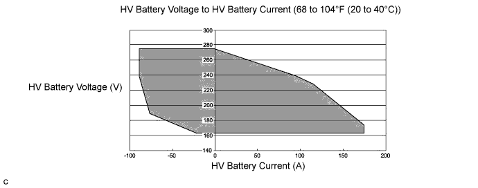
DTC P0A94-587 DC / DC Converter Performance |
| DTC No. | INF Code | DTC Detection Condition | Trouble Area |
| P0A94 | 587 | Voltages from HV battery voltage (VB) sensor and boost converter voltage (VL) sensor deviate Difference between "VL-Voltage before Boosting" and "Power Resource VB" is large when the boosting request is given. (1 trip detection logic) |
|
| DTC No. | Data List |
| P0A94-587 |
|
| Related DTCs | P0A94 (INF 587): Voltage (VB or VL) sensor deviation |
| Required sensors / components | Boost converter |
| Frequency of operation | - |
| Duration | TMC's intellectual property |
| MIL operation | 1 driving cycle |
| Sequence of operation | None |
| The monitor will run whenever the following DTCs are not present | TMC's intellectual property |
| Other conditions belong to TMC's intellectual property | - |
| TMC's intellectual property | - |
| Power management control ECU (HV CPU) | DTC P0A94 (INF 587) is not detected |
| 1.CHECK DTC OUTPUT (HV) |
Connect the Techstream to the DLC3.
Turn the power switch on (IG).
Enter the following menus: Powertrain / Hybrid Control / Trouble Codes.
Check if DTCs are output.
| Result | Proceed to |
| P0A94-587 only is output. Alternatively, P0A94- 587 and any DTCs other than P0A1F-129, P0A94-442 or P0A94-585 are output. | A |
| P0A94-587 and P0A1F-129 (HV battery voltage circuit malfunction) are output. | B |
| P0A94-587 and P0A94-442 (abnormal voltage execution value) are output. | C |
| P0A94-587 and P0A94-585 (boost converter voltage (VL) sensor performance problem) are output. | D |
Turn the power switch off.
|
| ||||
|
| ||||
|
| ||||
| A | |
 |
| 2.CLEAR DTC |
Connect the Techstream to the DLC3.
Turn the power switch on (IG).
Enter the following menus: Powertrain / Hybrid Control / Trouble Codes.
Read and record the DTCs and freeze frame data.
Clear DTCs and freeze frame data.
Turn the power switch off.
| NEXT | |
|
| 3.CHECK DTC OUTPUT (HV) |
Connect the Techstream to the DLC3.
Turn the power switch on (READY). (*1)
Enter the following menus: Powertrain / Hybrid Control / Data List (*2)
If both HV battery voltage (VB) and VL-Voltage before Boosting are less than 220 V, move the shift lever to D and depress both the accelerator pedal and brake pedal at the same time to raise them to 220 V or more. (*3)
Push the P position switch. (*4)
Set the air conditioning to MAX COOL and turn the headlights on. (*5)
Confirm that "Batt Pack Current Val" is more than 3 A. (*6)
Leave the vehicle for 15 seconds with the engine stopped during steps (*4) (*5) and (*6). (*7)
Enter the following menus: Powertrain / Hybrid Control / Trouble Codes. (*8)
Check if DTCs are output. (*9)
| Result | Proceed to |
| No DTCs are output, or DTCs other than the following are output. | A |
| P0A1F-129 (HV battery voltage circuit malfunction) is output. | B |
| P0A94-585 (boost converter voltage (VL) sensor performance problem) is output. | C |
| P3000-388 (discharge inhibition) is output. | D |
| P3004-132 (high voltage power supply line problem) is output. | E |
Turn the power switch off.
|
| ||||
|
| ||||
|
| ||||
|
| ||||
| A | |
|
| 4.CHECK DTC OUTPUT (HV) |
Turn the power switch on (READY).
Perform a road test that repeats full acceleration to 37 mph (60 km/h) and then braking to a complete stop three times. (*10)
Connect the Techstream to the DLC3.
Enter the following menus: Powertrain / Hybrid Control / Trouble Codes. (*11)
Check if DTCs are output. (*12)
| Result | Proceed to |
| No DTCs are output, or DTCs other than the following are output. | A |
| P0A1F-129 (HV battery voltage circuit malfunction) is output. | B |
| P0A94-585 (boost converter voltage (VL)) sensor performance problem) is output. | C |
| P3000-388 (discharge inhibition) is output. | D |
| P3004-132 (high voltage power supply line problem) is output. | E |
Turn the power switch off.
|
| ||||
|
| ||||
|
| ||||
|
| ||||
| A | |
|
| 5.READ VALUE USING TECHSTREAM |
Connect the Techstream to the DLC3.
Turn the power switch on (READY).
Enter the following menus: Powertrain / Hybrid Control / Data List
Select HV battery voltage (VB) , VL-Voltage before Boosting and VH-Voltage after Boosting in the Data List.
If both HV battery voltage (VB) and VL-Voltage before Boosting are less than 220 V, move the shift lever to D and depress both the accelerator pedal and brake pedal at the same time to raise them to 220 V or more.
Turn the engine off, push the P position switch, and read the Data List when the vehicle is stationary.
| Result | Proceed to |
| Both of the following are not satisfied. | A |
Both of the following are satisfied:
| B |
Both of the following are satisfied:
| C |
Turn the power switch off.
|
| ||||
|
| ||||
| A | |
|
| 6.CHECK FREEZE FRAME DATA |
Connect the Techstream to the DLC3.
Turn the power switch on (IG).
Enter the following menus: Powertrain / Hybrid Control / Trouble Codes.
Read the freeze frame data of DTC P0A94-587.
| Result | Proceed to |
| Both of the following are satisfied or both of the following are not satisfied. | A |
| "Power Resource VB" is less than 160 V or more than 285 V. | B |
| "VL-Voltage before Boosting" is less than 160 V or more than 285 V. | C |
Turn the power switch off.
|
| ||||
|
| ||||
| A | |
|
| 7.CHECK FREEZE FRAME DATA |
Connect the Techstream to the DLC3.
Turn the power switch on (IG).
Enter the following menus: Powertrain / Hybrid Control / Trouble Codes.
Read the freeze frame data of DTC P0A94-587.
| Result | Proceed to |
| Others (Freeze frame data is not stored). | A |
Both of the following are satisfied:
| B |
| Neither A nor B is satisfied. | C |
Turn the power switch off.
|
| ||||
|
| ||||
| A | |
|
| 8.READ VALUE USING TECHSTREAM |
Connect the Techstream to the DLC3.
Turn the power switch on (READY).
Enter the following menus: Powertrain / Hybrid Control / Data List
If both HV battery voltage (VB) and VL-Voltage before Boosting are less than 220 V, move the shift lever to D and depress both the accelerator pedal and brake pedal at the same time to raise them to 220 V or more.
Turn the engine off, push the P position switch, and read the Data List of all battery block and HV battery voltages, when the vehicle is stationary.
| Result | Proceed to |
Both of the following are satisfied:
| A |
| The preceding condition is not satisfied. | B |
Turn the power switch off.
|
| ||||
| A | ||
 | ||
| ||
