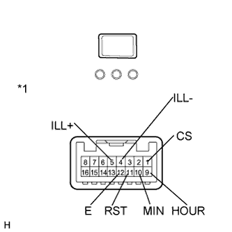
SATELLITE SWITCH > INSPECTION |
| 1. INSPECT TRIP SWITCH (w/o Headup Display) |
|
Measure the resistance according to the value(s) in the table below.
| Tester Connection | Condition | Specified Condition |
| 1 (CS) - 12 (E) | Unit change switch not pressed | 10 kΩ or higher |
| 1 (CS) - 12 (E) | Unit change switch pressed | Below 1 Ω |
| 9 (HOUR) - 12 (E) | Hour adjust switch not pressed | 10 kΩ or higher |
| 9 (HOUR) - 12 (E) | Hour adjust switch pressed | Below 1 Ω |
| 10 (MIN) - 12 (E) | Minute adjust switch not pressed | 10 kΩ or higher |
| 10 (MIN) - 12 (E) | Minute adjust switch pressed | Below 1 Ω |
| 11 (RST) - 12 (E) | Set switch not pressed | 10 kΩ or higher |
| 11 (RST) - 12 (E) | Set switch pressed | Below 1 Ω |
Apply battery voltage from the wire harness back side between the terminals of the switch, and check the lighting condition of the trip switch.
| Measurement Condition | Condition | Specified Condition |
| Battery positive (+) → 5 (ILL+) Battery negative (-) → 4 (ILL-) | Always | Trip switch illuminates |
| *1 | Trip Switch (w/o Headup Display) |
| 2. INSPECT TRIP SWITCH (w/ Headup Display) |
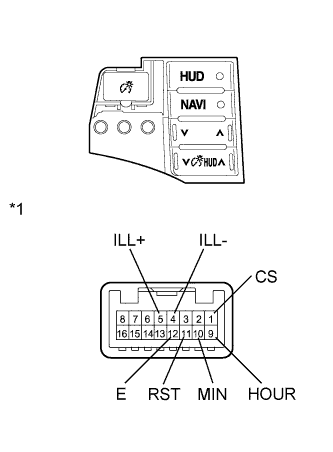 |
Measure the resistance according to the value(s) in the table below.
| Tester Connection | Condition | Specified Condition |
| 1 (CS) - 12 (E) | Unit change switch pressed | Below 1 Ω |
| 1 (CS) - 12 (E) | Unit change switch not pressed | 10 kΩ or higher |
| 9 (HOUR) - 12 (E) | Hour adjust switch pressed | Below 1 Ω |
| 9 (HOUR) - 12 (E) | Hour adjust switch not pressed | 10 kΩ or higher |
| 10 (MIN) - 12 (E) | Minute adjust switch pressed | Below 1 Ω |
| 10 (MIN) - 12 (E) | Minute adjust switch not pressed | 10 kΩ or higher |
| 11 (RST) - 12 (E) | Set switch pressed | Below 1 Ω |
| 11 (RST) - 12 (E) | Set switch not pressed | 10 kΩ or higher |
Apply battery voltage from the wire harness back side between the terminals of the switch, and check the lighting condition of the trip switch.
| Measurement Condition | Condition | Specified Condition |
| Battery positive (+) → 5 (ILL+) Battery negative (-) → 4 (ILL-) | Always | Trip switch illuminates |
| *1 | Component without harness connected (Trip Switch) |