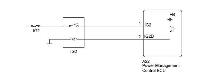
DTC P2532-772 Ignition Switch Run Position Circuit High |
| DTC No. | INF Code | DTC Detection Condition | Trouble Area |
| P2532 | 772 | Although the power management control ECU is sending a signal to open the IG2 relay, voltage is applied to the IG2 terminal. Although the power switch is turned off, the HV control system is not turned off. (1 trip detection logic) |
|
| 1.CHECK HARNESS AND CONNECTOR (+B SHORT) |
Disconnect connector A22 from the power management control ECU.
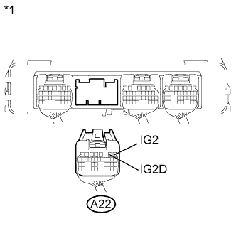 |
Measure the voltage according to the value(s) in the table below.
| *1 | Rear view of wire harness connector (to Power Management Control ECU) |
| Tester Connection | Switch Condition | Specified Condition |
| A22-1(IG2) - Body ground | Power switch off | Below 1 V |
| A22-2(IG2D) - Body ground | Power switch off | Below 1 V |
| Result | Proceed to |
| NG | A |
| OK | B |
Connect the power management control ECU connector.
|
| ||||
| A | |
 |
| 2.CHECK HARNESS AND CONNECTOR (POWER MANAGEMENT CONTROL ECU - NO. 2 INTEGRATION RELAY) |
Disconnect connector A22 from the power management control ECU.
Remove the integration no. 2 relay from the engine room junction block assembly.
|
Measure the voltage according to the value(s) in the table below.
| *1 | Rear view of wire harness connector (to Power Management Control ECU) |
| Tester Connection | Switch Condition | Specified Condition |
| A22-1(IG2) - Body ground | Power switch off | Below 1 V |
| A22-2(IG2D) - Body ground | Power switch off | Below 1 V |
Install the integration no. 2 relay.
Connect the power management control ECU connector.
|
| ||||
| OK | ||
 | ||
| ||
