Home › Brake › BRAKE CONTROL / DYNAMIC CONTROL SYSTEMS › REAR SPEED SENSOR

REAR SPEED SENSOR > INSTALLATION

for Preparation Click here


HINT:
  1. If the sensor rotor needs to be replaced, replace it together with the rear axle hub and bearing assembly.
  2. The rear speed sensor is a component of the rear axle hub and bearing assembly. If the sensor malfunctions, replace the rear axle hub and bearing assembly.


1. INSTALL REAR AXLE HUB AND BEARING ASSEMBLY
  1. Install the rear axle hub and bearing assembly .

    HINT:
    The rear speed sensor is a component of the rear axle hub and bearing assembly. If the sensor malfunctions, replace the rear axle hub and bearing assembly.


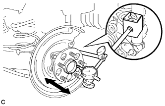
2. INSPECT REAR AXLE HUB BEARING LOOSENESS


    C207082
  1. Using a dial indicator, check for looseness near the center of the axle hub.

    Maximum looseness:
    0.05 mm (0.00196 in.)

    NOTICE:
    1. Ensure that the dial indicator is set perpendicular to the measurement surface.
    2. Keep the magnet of the dial indicator away from the rear axle hub and bearing (rear speed sensor).

    HINT:
    If the looseness exceeds the maximum, replace the rear axle hub and bearing assembly.


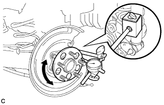
3. INSPECT REAR AXLE HUB RUNOUT


    C207083
  1. Using a dial indicator, check for runout on the surface of the axle hub outside the rear axle hub bolt.

    Maximum runout:
    0.05 mm (0.00196 in.)

    NOTICE:
    1. Ensure that the dial indicator is set perpendicular to the measurement surface.
    2. Make sure to install the tip of the dial indicator towards the outside of the rear axle hub bolt.
    3. Keep the magnet of the dial indicator away from the rear axle hub and bearing (rear speed sensor).

    HINT:
    If the runout exceeds the maximum, replace the rear axle hub and bearing assembly.


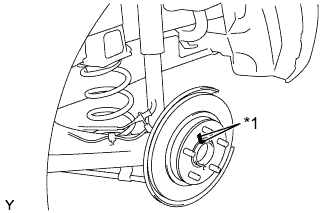
4. INSTALL REAR DISC


    C151123E03
  1. Align the matchmarks of the disc and axle hub, and install the disc.
    Text in Illustration 
    *1
    Matchmark

    NOTICE:
    When replacing the disc with a new one, select the installation position where the rear disc has minimal runout.


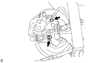
5. INSTALL REAR DISC BRAKE CALIPER ASSEMBLY


    C207078
  1. Install the rear disc brake caliper assembly with the 2 bolts.

    Torque:
    57 N*m{ 585 kgf*cm , 42 ft.*lbf }


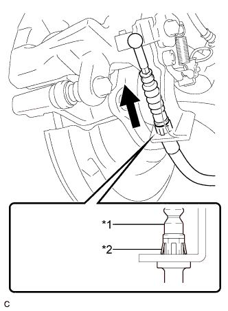
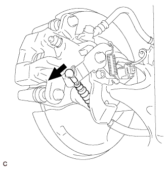
6. CONNECT NO. 3 PARKING BRAKE CABLE ASSEMBLY


    C155547E03
  1. Install the No. 3 parking brake cable assembly to the rear disc brake cylinder assembly.
    Text in Illustration 
    *1
    No. 3 Parking Brake Cable Assembly
    *2
    Clip

    HINT:
    Be sure to engage the No. 3 parking brake cable assembly clip onto the rear disc brake cylinder assembly as shown in the illustration.


    C155545E02
  1. Connect the No. 3 parking brake cable assembly to the rear disc brake cylinder assembly.


7. CONNECT REAR SPEED SENSOR WIRE


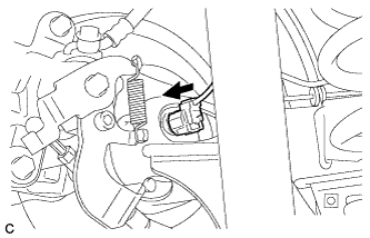
    C208054
  1. Connect the rear speed sensor wire connector to the rear speed sensor.


8. ADJUST PARKING BRAKE PEDAL TRAVEL
  1. Remove the lower instrument panel finish panel assembly .

  1. Completely release the parking brake pedal.


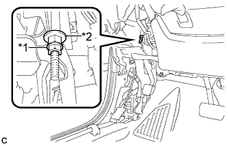
    C206641E01
  1. Loosen the lock nut and the adjusting nut to completely release the parking brake cable.
    Text in Illustration 
    *1
    Lock Nut
    *2
    Adjusting Nut

  1. Turn the adjusting nut until the parking brake pedal travel is corrected to be within the specified range.

    Parking brake pedal travel:
    8 to 11 notches at 300 N (31 kgf, 67.5 lbf)


    C206641E01
  1. Using a wrench or an equivalent tool, hold the adjusting nut and tighten the lock nut.
    Text in Illustration 
    *1
    Lock Nut
    *2
    Adjusting Nut

    Torque:
    5.4 N*m{ 55 kgf*cm , 48 in.*lbf }

  1. Operate the parking brake pedal 3 to 4 times, and check the parking brake pedal travel.

  1. Check whether the parking brake drags or not.

  1. Install the lower instrument panel finish panel assembly .


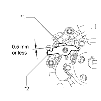
9. INSPECT REAR DISC BRAKE CYLINDER OPERATION LEVER AND STOPPER CLEARANCE


    C155526E03
  1. Release the parking brake lever and check that the clearance measurement between the rear disc brake cylinder operation lever and the stopper is within the specified range.
    Text in Illustration 
    *1
    Stopper
    *2
    Operation Lever

    Clearance:
    0.5 mm (0.0197 in.) or less

    If the clearance is not within the specified range, replace the rear disc brake caliper assembly.


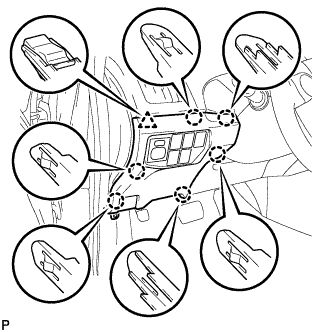
10. INSTALL LOWER INSTRUMENT PANEL FINISH PANEL ASSEMBLY
  1. Connect each connector.

  1. Engage the clamp.

  1. Engage the 2 guides and claw to connect the hood lock control cable.


    B298864
  1. Engage the 6 claws and clip.

  1. Install the lower instrument panel finish panel assembly with the screw <C>.


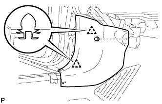
11. INSTALL COWL SIDE TRIM SUB-ASSEMBLY LH


    B227764
  1. Engage the 2 clips.

  1. Install the cowl side trim board LH with the clip.


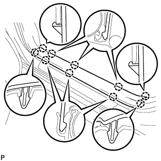
12. INSTALL FRONT DOOR SCUFF PLATE LH


    B227761
  1. Engage the 10 claws to install the front door scuff plate LH.


13. INSTALL REAR WHEEL

Torque:
103 N*m{ 1050 kgf*cm , 76 ft.*lbf }


14. CONNECT CABLE TO AUXILIARY BATTERY NEGATIVE TERMINAL
  1. Connect the cable to the auxiliary battery negative (-) terminal.

  1. Connect the reservoir level switch connector.

  1. Clear the DTCs (Click here).


15. INSTALL REAR NO. 3 FLOOR BOARD


    B227791
  1. Engage the 2 guides to install the rear No. 3 floor board.


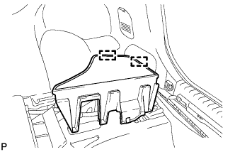
16. INSTALL REAR DECK FLOOR BOX
  1. Install the rear deck floor box.


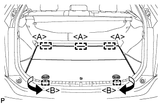
17. INSTALL REAR NO. 2 FLOOR BOARD (for Separate Type)


    B227788E01
  1. Engage the 3 guides <A>.

  1. Engage the 2 guides <B> and install the rear No. 2 floor board as shown in the illustration.


18. CHECK FOR SPEED SENSOR SIGNAL
(Click here)