 |
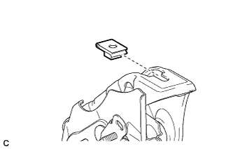
Install the nut to the brake pedal support assembly.
BRAKE PEDAL > INSTALLATION |
| 1. INSTALL BRAKE PEDAL SUPPORT ASSEMBLY |
|
Install the nut to the brake pedal support assembly.
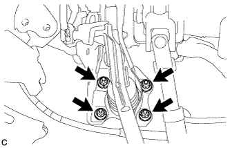 |
Install the brake pedal support assembly with the 4 nuts.
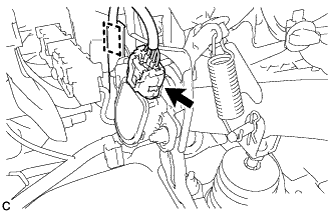 |
Engage the clamp and connect the connector to the brake pedal stroke sensor assembly.
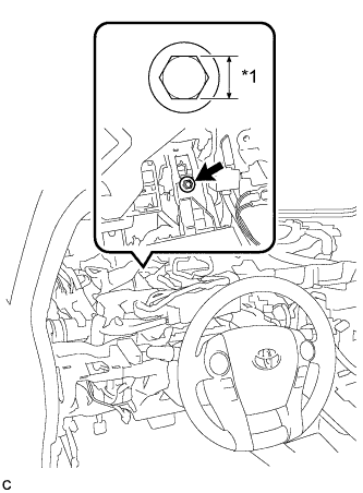 |
Install the brake pedal support assembly to the instrument panel reinforcement with the bolt.
| *1 | Bolt Width |
| Bolt Variation | Bolt Width |
| Bolt A | 14 mm (0.551 in.) |
| Bolt B | 12 mm (0.472 in.) |
| 2. INSTALL INSTRUMENT PANEL JUNCTION BLOCK ASSEMBLY |
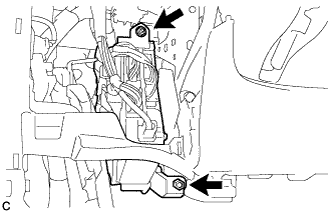 |
Install the instrument panel junction block assembly with the bolt and nut.
| 3. INSTALL PUSH ROD PIN |
Apply lithium soap base glycol grease to the push rod pin and installation hole of the brake pedal support assembly.
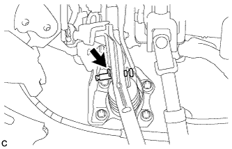 |
Install the push rod pin and a new clip to connect the push rod clevis to the brake pedal support assembly.
| 4. INSTALL BRAKE PEDAL RETURN SPRING |
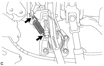 |
Install the brake pedal return spring to the brake pedal support assembly and push rod pin.
| 5. INSTALL STOP LIGHT SWITCH MOUNTING ADJUSTER |
| 6. INSTALL STOP LIGHT SWITCH ASSEMBLY |
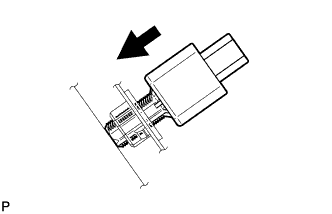 |
Insert the stop light switch assembly until the threaded sleeve hits the pedal.
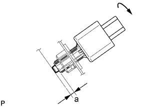 |
Make a quarter turn clockwise to install the stop light switch assembly.
Connect the connector.
Check the protrusion of the plunger.
| Area | Measurement |
| a | 0.5 to 2.6 mm (0.0197 to 0.102 in.) |
| 7. INSTALL UPPER INSTRUMENT PANEL ASSEMBLY |
| 8. INSPECT AND ADJUST BRAKE PEDAL |
| 9. INSTALL NO. 1 INSTRUMENT PANEL UNDER COVER SUB-ASSEMBLY |
Connect each connector.
Engage the guide and claw.
Install the No. 1 instrument panel under cover sub-assembly with the 2 screws <D>.
| 10. PERFORM INITIALIZATION AND CALIBRATION OF LINEAR SOLENOID VALVE |