 |
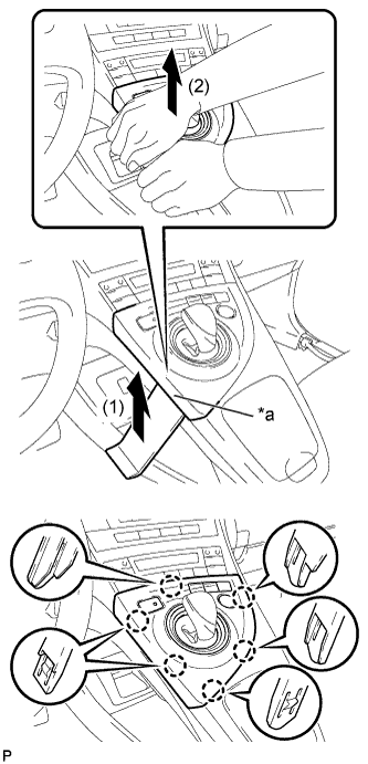
Using a moulding remover, slightly lift the panel at the position shown in the illustration.
| *a | Lift slightly |
BACK-UP BATTERY > REMOVAL |
| 1. REMOVE INTEGRATION CONTROL AND PANEL ASSEMBLY |
|
Using a moulding remover, slightly lift the panel at the position shown in the illustration.
| *a | Lift slightly |
Pull the integration control and panel assembly in the direction indicated by the arrow to disengage the 6 claws.
Disconnect each connector and remove the integration control and panel assembly.
| 2. REMOVE LOWER CENTER INSTRUMENT CLUSTER FINISH PANEL SUB-ASSEMBLY |
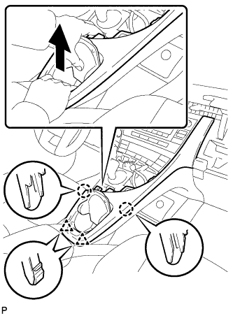 |
Pull the lower center instrument cluster finish panel sub-assembly in the direction indicated by the arrow to disengage the 2 claws and 2 clips.
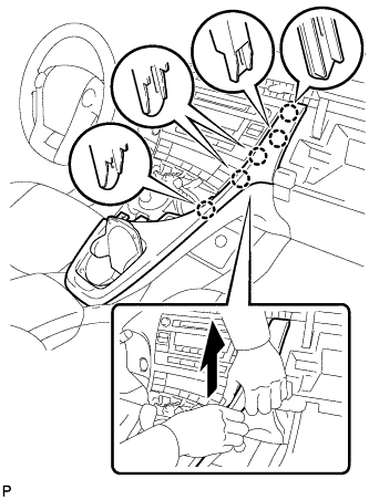 |
Pull the lower center instrument cluster finish panel sub-assembly in the direction indicated by the arrow to disengage the 5 claws and remove the lower center instrument cluster finish panel sub-assembly.
| 3. REMOVE INSTRUMENT CLUSTER FINISH PANEL GARNISH |
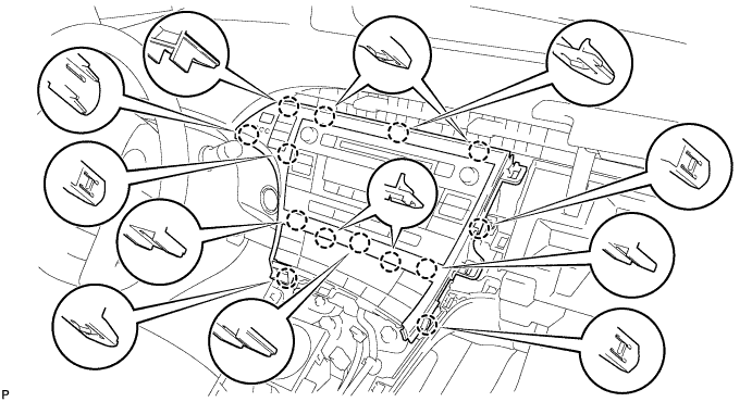
Disengage the 14 claws.
Disconnect the connector and remove the instrument cluster finish panel garnish.
| 4. REMOVE UPPER INSTRUMENT PANEL FINISH PANEL SUB-ASSEMBLY |
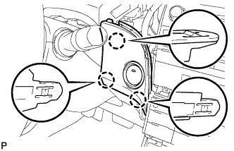 |
Disengage the 3 claws.
Disconnect the connector and remove the upper instrument panel finish panel sub-assembly.
| 5. REMOVE RADIO RECEIVER WITH BRACKET (w/o Navigation System) |
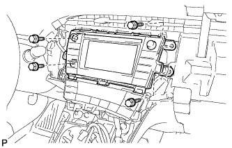 |
Remove the 4 bolts.
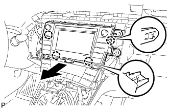 |
Disengage the 4 claws as shown in the illustration.
Disconnect each connector and remove the radio and display receiver assembly with bracket.
| 6. REMOVE NAVIGATION RECEIVER WITH BRACKET (w/ Navigation System) |
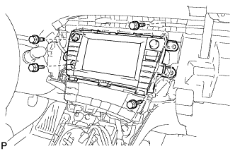 |
Remove the 4 bolts.
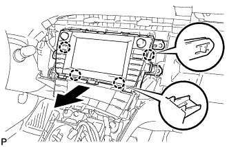 |
Disengage the 4 claws and remove the navigation receiver with bracket as shown in the illustration.
Disconnect each connector.
| 7. REMOVE BACK-UP BATTERY WITH BRACKET |
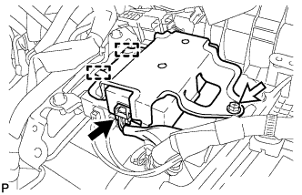 |
Disconnect the connector.
Remove the bolt.
Disengage the 2 guides and remove the back-up battery with bracket
| 8. REMOVE BACK-UP BATTERY |
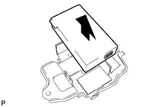 |
Remove the back-up battery from the No. 1 telephone bracket as shown in the illustration.
| 9. REMOVE NO. 1 TELEPHONE BRACKET |