DTC P082B-575 Gear Lever X Position Circuit Low |
DTC P082C-576 Gear Lever X Position Circuit High |
DTC P082E-571 Gear Lever Y Position Circuit Low |
DTC P082F-572 Gear Lever Y Position Circuit High |
DTC P181A-596 Gear Lever X Position Circuit "A" / "B" Correlation |
DTC P181B-595 Gear Lever Y Position Circuit "A" / "B" Correlation |
DTC P182B-577 Gear Lever X Position "B" Circuit Low |
DTC P182C-578 Gear Lever X Position "B" Circuit High |
DTC P182E-573 Gear Lever Y Position "B" Circuit Low |
DTC P182F-574 Gear Lever Y Position "B" Circuit High |


| DTC No. | INF Code | DTC Detection Condition | Trouble Area |
| P082B | 575 | Open or GND short in select main sensor circuit (1 trip detection logic) |
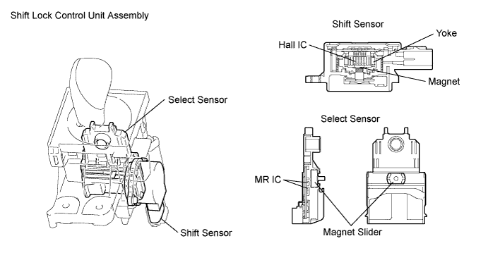
|
| P082C | 576 | +B short in select main sensor circuit (1 trip detection logic) | |
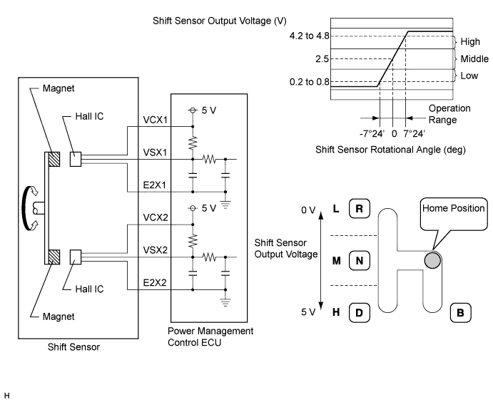
| P082E | 571 | Open or GND short in shift main sensor circuit (1 trip detection logic) | |
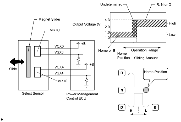
| P082F | 572 | +B short in shift main sensor circuit (1 trip detection logic) | |
| P181A | 596 | Difference between select main sensor value and select sub sensor value is large (1 trip detection logic) | |
| P181B | 595 | Difference between shift main sensor value and shift sub sensor value is large (1 trip detection logic) | |
| P182B | 577 | Open or GND short in select sub sensor circuit (1 trip detection logic) | |
| P182C | 578 | +B short in select sub sensor circuit (1 trip detection logic) | |
| P182E | 573 | Open or GND short in shift sub sensor circuit (1 trip detection logic) | |
| P182F | 574 | +B short in shift sub sensor circuit (1 trip detection logic) |
| DTC No. | Data List |
| P082B-575 |
|
| P082C-576 | |
| P082E-571 | |
| P082F-572 | |
| P181A-596 | |
| P181B-595 | |
| P182B-577 | |
| P182C-578 | |
| P182E-573 | |
| P182F-574 |
| R position (Main) | Home or N position (Main) | D or B position (Main) | R position (Sub) | Home or N position (Sub) | D or B position (Sub) | Trouble Area |
| 0.3 to 1.8 V | 2.0 to 3.0 V | 3.2 to 4.8 V | 0.3 to 1.8 V | 2.0 to 3.0 V | 3.2 to 4.8 V | Correct shift sensor voltage |
| 0 to 0.3 V | 0 to 0.3 V | 0 to 0.3 V | 0.3 to 1.8 V | 2.0 to 3.0 V | 3.2 to 4.8 V | Open in VCX1 circuit GND short in VSX1 circuit |
| 0.3 to 1.8 V | 2.0 to 3.0 V | 3.2 to 4.8 V | 0 to 0.3 V | 0 to 0.3 V | 0 to 0.3 V | Open in VCX2 circuit GND short in VSX2 circuit |
| 4.8 to 5.0 V | 4.8 to 5.0 V | 4.8 to 5.0 V | 0.3 to 1.8 V | 2.0 to 3.0 V | 3.2 to 4.8 V | Open in VSX1 circuit Open in E2X1 circuit |
| 0.3 to 1.8 V | 2.0 to 3.0 V | 3.2 to 4.8 V | 4.8 to 5.0 V | 4.8 to 5.0 V | 4.8 to 5.0 V | Open in VSX2 circuit Open in E2X2 circuit |
| R, N or D Position Select Main) | Home or B Position Select Main) | R, N or D Position Select Sub) | Home or B Position Select Sub) | Trouble Area |
| 2.9 to 4.3 V | 1.0 to 1.6 V | 2.9 to 4.3 V | 1.0 to 1.6 V | Correct select sensor voltage |
| 0 to 0.5 V | 0 to 0.5 V | 2.9 to 4.3 V | 1.0 to 1.6 V | Open in VCX3 circuit Open or GND short in VSX3 circuit |
| 2.9 to 4.3 V | 1.0 to 1.6 V | 0 to 0.5 V | 0 to 0.5 V | Open in VCX4 circuit Open or GND short in VSX4 circuit |
| 4.9 to 5 V | 4.9 to 5 V | 2.9 to 4.3 V | 1.0 to 1.6 V | +B short in VSX3 circuit |
| 2.9 to 4.3 V | 1.0 to 1.6 V | 4.9 to 5 V | 4.9 to 5 V | +B short in VSX4 circuit |

| 1.READ VALUE USING TECHSTREAM (SHIFT SENSOR MAIN, SHIFT SENSOR SUB) |
Connect the Techstream to the DLC3.
Turn the power switch on (IG).
Enter the following menus: Powertrain / Hybrid Control / Data List / Shift Sensor Main, Shift Sensor Sub.
Read the Data List.
| Tester Display | Condition | Specified Condition |
| Shift Sensor Main | R position | 0.3 to 1.8 V |
| Home or N position | 2.0 to 3.0 V | |
| D or B position | 3.2 to 4.8 V | |
| Shift Sensor Sub | R position | 0.3 to 1.8 V |
| Home or N position | 2.0 to 3.0 V | |
| D or B position | 3.2 to 4.8 V |
Turn the power switch off.
|
| ||||
| OK | |
| 2.READ VALUE USING TECHSTREAM (SHIFT SENSOR SELECT MAIN, SHIFT SENSOR SELECT SUB) |
Connect the Techstream to the DLC3.
Turn the power switch on (IG).
Enter the following menus: Powertrain / Hybrid Control / Data List / Shift Sensor Select Main, Shift Sensor Select Sub.
Read the Data List.
| Tester Display | Condition | Specified Condition |
| Shift Sensor Select Main | R, N or D Position | 2.9 to 4.3 V |
| Home or B Position | 1.0 to 1.6 V | |
| Shift Sensor Select Sub | R, N or D Position | 2.9 to 4.3 V |
| Home or B Position | 1.0 to 1.6 V |
Turn the power switch off.
|
| ||||
| OK | |
| 3.REPLACE SHIFT LOCK CONTROL UNIT ASSEMBLY |
| NEXT | |
| 4.CLEAR DTC |
Connect the Techstream to the DLC3.
Turn the power switch on (IG).
Enter the following menus: Powertrain / Hybrid Control / Trouble Codes.
Read and record the DTCs and freeze frame data.
Clear DTCs and freeze frame data.
Turn the power switch off.
| NEXT | |
| 5.CHECK DTC OUTPUT (HV) |
Connect the Techstream to the DLC3.
Turn the power switch on (IG).
With the brake pedal depressed, slowly move the shift lever as follows to select each shift state: N → R → N → D → B.
Push the P position switch (transmission shift main switch) to select park (P).
Enter the following menus: Powertrain / Hybrid Control / Trouble Codes.
Check if DTCs are output.
| Result | Proceed to |
| No DTCs are output. | A |
| P082B-575, P082C-576, P082E-571, P082F-572, P181A-596, P181B-595, P182B-577, P182C-578, P182E-573 or P182F-574 is output again. | B |
Turn the power switch off.
|
| ||||
| A | ||
| ||
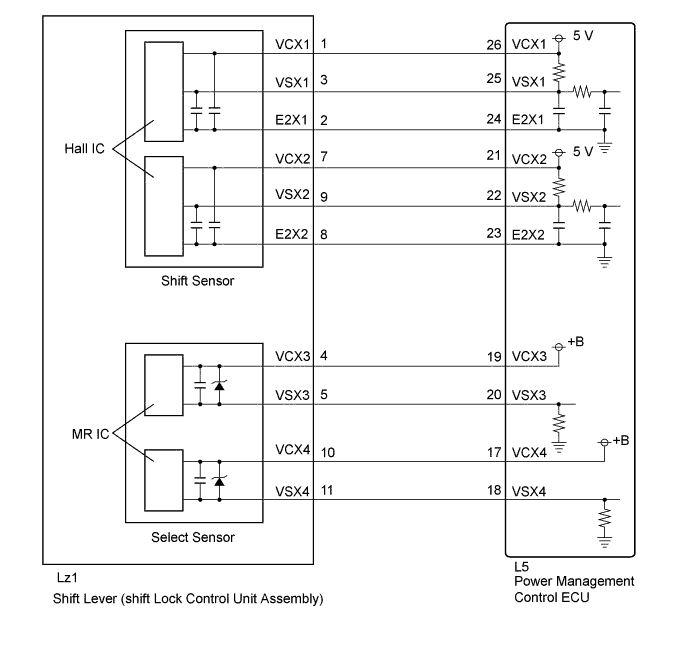
| 6.CHECK HARNESS AND CONNECTOR (POWER MANAGEMENT CONTROL ECU - SHIFT SENSOR) |
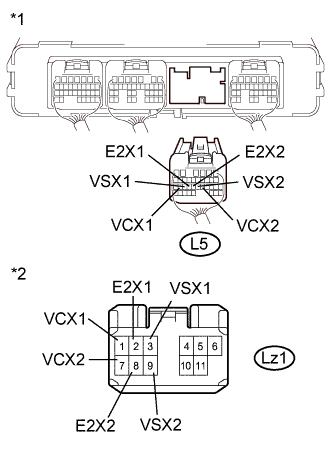
Disconnect connector L5 from the power management control ECU.
Disconnect connector Lz1 from the shift lever (shift lock control unit assembly).
![]() |
Measure the resistance according to the value(s) in the table below.
| Tester Connection | Switch Condition | Specified Condition |
| L5-26 (VCX1) - Lz1-1 (VCX1) | Power switch off | Below 1 Ω |
| L5-25 (VSX1) - Lz1-3 (VSX1) | Power switch off | Below 1 Ω |
| L5-24 (E2X1) - Lz1-2 (E2X1) | Power switch off | Below 1 Ω |
| L5-21 (VCX2) - Lz1-7 (VCX2) | Power switch off | Below 1 Ω |
| L5-22 (VSX2) - Lz1-9 (VSX2) | Power switch off | Below 1 Ω |
| L5-23 (E2X2) - Lz1-8 (E2X2) | Power switch off | Below 1 Ω |
| Tester Connection | Switch Condition | Specified Condition |
| L5-26 (VCX1) or Lz1-1 (VCX1) - Body ground and other terminals | Power switch off | 10 kΩ or higher |
| L5-25 (VSX1) or Lz1-3 (VSX1) - Body ground and other terminals | Power switch off | 10 kΩ or higher |
| L5-24 (E2X1) or Lz1-2 (E2X1) - Body ground and other terminals | Power switch off | 10 kΩ or higher |
| L5-21 (VCX2) or Lz1-7 (VCX2) - Body ground and other terminals | Power switch off | 10 kΩ or higher |
| L5-22 (VSX2) or Lz1-9 (VSX2) - Body ground and other terminals | Power switch off | 10 kΩ or higher |
| L5-23 (E2X2) or Lz1-8 (E2X2) - Body ground and other terminals | Power switch off | 10 kΩ or higher |
| *1 | Rear view of wire harness connector (to Power Management Control ECU) |
| *2 | Front view of wire harness connector (to Shift Lock Control Unit Assembly) |
Connect the shift lever (shift lock control unit assembly) connector.
Connect the power management control ECU connector.
|
| ||||
| OK | |
| 7.CHECK POWER MANAGEMENT CONTROL ECU (VCX1, VCX2 VOLTAGE) |
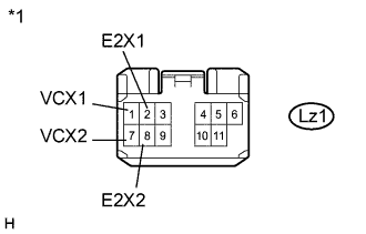
Disconnect connector Lz1 from the shift lever (shift lock control unit assembly).
Turn the power switch on (IG).
![]() |
Measure the voltage according to the value(s) in the table below.
| Tester Connection | Switch Condition | Specified Condition |
| Lz1-1 (VCX1) - Lz1-2 (E2X1) | Power switch on (IG) | 4.5 to 5.5 V |
| Lz1-7 (VCX2) - Lz1-8 (E2X2) | Power switch on (IG) | 4.5 to 5.5 V |
| *1 | Front view of wire harness connector (to Shift Lock Control Unit Assembly) |
Connect the shift lever (shift lock control unit assembly) connector.
|
| ||||
| OK | |
| 8.REPLACE SHIFT LOCK CONTROL UNIT ASSEMBLY |
Replace the shift lock control unit assembly (Click here).
| NEXT | |
| 9.CLEAR DTC |
Connect the Techstream to the DLC3.
Turn the power switch on (IG).
Enter the following menus: Powertrain / Hybrid Control / Trouble Codes.
Read and record the DTCs and freeze frame data.
Clear DTCs and freeze frame data.
Turn the power switch off.
| NEXT | |
| 10.CHECK DTC OUTPUT (HV) |
Connect the Techstream to the DLC3.
Turn the power switch on (IG).
Slowly move the shift lever as follows: N → R → N → D → B
Enter the following menus: Powertrain / Hybrid Control / Trouble Codes.
Check if DTCs are output.
| Result | Proceed to |
| No DTCs are output. | A |
| P082B-575, P082C-576, P082E-571, P082F-572, P181A-596, P181B-595, P182B-577, P182C-578, P182E-573 or P182F-574 is output again. | B |
Turn the power switch off.
|
| ||||
| A | ||
| ||
| 11.CHECK HARNESS AND CONNECTOR (POWER MANAGEMENT CONTROL ECU - SELECT SENSOR) |
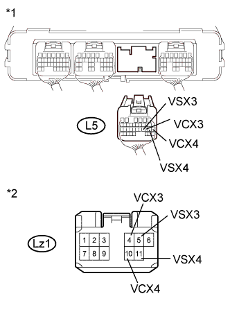
Disconnect connector L5 from the power management control ECU.
Disconnect connector Lz1 from the shift lever (shift lock control unit assembly).
![]() |
Measure the resistance according to the value(s) in the table below.
| Tester Connection | Switch Condition | Specified Condition |
| L5-19 (VCX3) - Lz1-4 (VCX3) | Power switch off | Below 1 Ω |
| L5-20 (VSX3) - Lz1-5 (VSX3) | Power switch off | Below 1 Ω |
| L5-17 (VCX4) - Lz1-10 (VCX4) | Power switch off | Below 1 Ω |
| L5-18 (VSX4) - Lz1-11 (VSX4) | Power switch off | Below 1 Ω |
| Tester Connection | Switch Condition | Specified Condition |
| L5-19 (VCX3) or Lz1-4 (VCX3) - Body ground and other terminals | Power switch off | 10 kΩ or higher |
| L5-20 (VSX3) or Lz1-5 (VSX3) - Body ground and other terminals | Power switch off | 10 kΩ or higher |
| L5-17 (VCX4) or Lz1-10 (VCX4) - Body ground and other terminals | Power switch off | 10 kΩ or higher |
| L5-18 (VSX4) or Lz1-11 (VSX4) - Body ground and other terminals | Power switch off | 10 kΩ or higher |
| *1 | Rear view of wire harness connector (to Power Management Control ECU) |
| *2 | Front view of wire harness connector (to Shift Lock Control Unit Assembly) |
Connect the shift lever (shift lock control unit assembly) connector.
Connect the power management control ECU connector.
|
| ||||
| OK | |
| 12.CHECK POWER MANAGEMENT CONTROL ECU (VCX3, VCX4 VOLTAGE) |
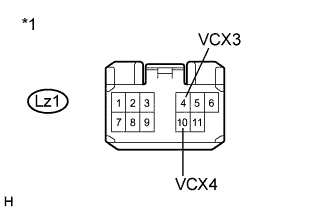
Disconnect connector Lz1 from the shift lever (shift lock control unit assembly).
Turn the power switch on (IG).
![]() |
Measure the voltage according to the value(s) in the table below.
| Tester Connection | Switch Condition | Specified Condition |
| Lz1-4 (VCX3) - Body ground | Power switch on (IG) | 9 to 14 V |
| Lz1-10 (VCX4) - Body ground | Power switch on (IG) | 9 to 14 V |
| *1 | Front view of wire harness connector (to Shift Lock Control Unit Assembly) |
Connect the shift lever (shift lock control unit assembly) connector.
|
| ||||
| OK | |
| 13.REPLACE SHIFT LOCK CONTROL UNIT ASSEMBLY |
Replace the shift lock control unit assembly (Click here).
| NEXT | |
| 14.CLEAR DTC |
Connect the Techstream to the DLC3.
Turn the power switch on (IG).
Enter the following menus: Powertrain / Hybrid Control / Trouble Codes.
Read and record the DTCs and freeze frame data.
Clear DTCs and freeze frame data.
Turn the power switch off.
| NEXT | |
| 15.CHECK DTC OUTPUT (HV) |
Connect the Techstream to the DLC3.
Turn the power switch on (IG).
With the brake pedal depressed, slowly move the shift lever as follows to select each shift state: N → R → N → D → B.
Push the P position switch (transmission shift main switch) to select park (P).
Enter the following menus: Powertrain / Hybrid Control / Trouble Codes.
Check if DTCs are output.
| Result | Proceed to |
| No DTCs are output. | A |
| P082B-575, P082C-576, P082E-571, P082F-572, P181A-596, P181B-595, P182B-577, P182C-578, P182E-573 or P182F-574 is output again. | B |
Turn the power switch off.
|
| ||||
| A | ||
| ||