Home › Engine / Hybrid System › HYBRID / BATTERY CONTROL › HYBRID CONTROL SYSTEM

DTC    P0A78-565    Drive Motor "A" Inverter Performance

for Preparation Click here


DESCRIPTION

For a description of the inverter, .
If an overvoltage occurs in the motor inverter or generator inverter, the MG ECU detects it and transmits this information to the power management control ECU (HV CPU).

DTC No.
INF Code
DTC Detection Condition
Trouble Area
P0A78
565
Motor inverter overvoltage signal is detected (VH sensor circuit malfunction) and voltage after boosting does not change for a certain period of time.
(1 trip detection logic)
Inverter with converter assembly

Related Data List 
DTC No.
Data List
P0A78-565
VH-Voltage after Boosting

MONITOR DESCRIPTION

If the motor inverter detects a circuit malfunction, it will transmit a motor inverter overvoltage signal to the MG ECU. Upon receiving this signal, the power management control ECU (HV CPU) will illuminate the MIL and set a DTC.

MONITOR STRATEGY


Related DTCs
P0A78 (INF 565): OVH detection (Voltage (VH) sensor malfunction)
Required sensors / components
Motor inverter
Frequency of operation
Continuous
Duration
TMC's intellectual property
MIL operation
1 driving cycle
Sequence of operation
None

TYPICAL ENABLING CONDITIONS


The monitor will run whenever the following DTCs are not present
TMC's intellectual property
Other conditions belong to TMC's intellectual property
-

TYPICAL MALFUNCTION THRESHOLDS


Other conditions belong to TMC's intellectual property
-

COMPONENT OPERATING RANGE


Power management control ECU (HV CPU)
DTC P0A78 (INF 565) is not detected

CONFIRMATION DRIVING PATTERN


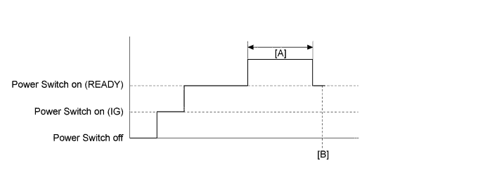
A309990E01

  1. Connect the Techstream to the DLC3.
  2. Turn the power switch on (IG) and turn the Techstream on.
  3. Clear the DTCs (even if no DTCs are stored, perform the clear DTC procedure).
  4. Turn the power switch off and wait for 30 seconds or more.
  5. Turn the power switch on (IG) and turn the Techstream on.
  6. Turn the power switch on (READY).
  7. With park (P) selected, and engine stopped, depress the accelerator pedal to start the engine. [A]
  8. Enter the following menus: Powertrain / Hybrid Control / Trouble Codes. [B]
  9. Read the current DTCs.

    HINT:
    1. If a current DTC is output, the system is malfunctioning.
    2. If a current DTC is not output and want to confirm permanent DTC, perform the following procedure.

  10. Check that permanent DTCs are cleared.
  11. If the permanent DTCs are not cleared, perform a universal trip, and then check for permanent DTCs again.

INSPECTION PROCEDURE

HINT:
After the repair, clear the DTCs and perform the following procedure to check that DTCs are not output.
  1. With the vehicle engine stopped, the power switch on (READY) and park (P) selected, depress the accelerator pedal to start the engine.

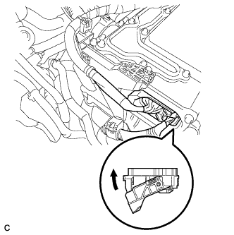
1.CHECK CONNECTOR CONNECTION CONDITION (INVERTER WITH CONVERTER ASSEMBLY CONNECTOR)
A214648

CAUTION:
Be sure to wear insulated gloves.

  1. Check that the service plug grip is not installed.

    NOTICE:
    After removing the service plug grip, do not turn the power switch on (READY), unless instructed by the repair manual because this may cause a malfunction.

NOTICE:
Before disconnecting the connector, confirm that it is properly connected by checking that the locking claws are engaged and that the connector does not pull out.

  1. Check the connection of the low voltage connector of the inverter with converter assembly.

    OK:
    The connector is connected securely and there are no contact problems.

    HINT:
    When connecting the connector, insert it with the locking lever in the raised position. Rotate the lever downward and make sure that the connector is pulled into its socket. When the locking lever is in its fully closed position, a click will be heard as its locking claws engage. After the click is heard, pull up on the connector to confirm that it is properly connected.


NG
CONNECT SECURELY
OK

REPLACE INVERTER WITH CONVERTER ASSEMBLY (Click here)