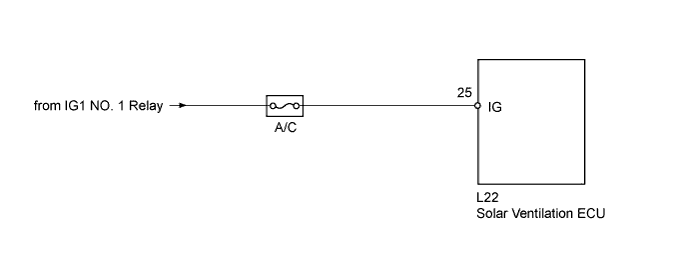
SOLAR VENTILATION SYSTEM > IG Signal Circuit |
| 1.READ VALUE USING TECHSTREAM |
Connect the Techstream to the DLC3.
Turn the power switch on (IG).
Turn the Techstream on.
Enter the following menus: Body Electrical / Air Conditioner / Data List.
Check the value(s) by referring to the table below.
| Tester Display | Measurement Item/Range | Normal Condition | Diagnostic Note |
| Solar IG Status | Solar ventilation ECU IG status / OFF or ON | OFF: Power switch off ON: Power switch on (IG) | When OFF is displayed, a malfunction in the solar ventilation ECU is suspected. |
| Result | Proceed to |
| NG | A |
| OK (When troubleshooting according to Problem Symptoms Table (for Solar Ventilation System)) | B |
| OK (When troubleshooting according to Problem Symptoms Table (for Air Conditioning System)) | C |
|
| ||||
|
| ||||
| A | |
 |
| 2.CHECK HARNESS AND CONNECTOR (SOLAR VENTILATION ECU - BATTERY) |
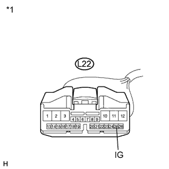 |
Disconnect the solar ventilation ECU connector.
Measure the voltage according to the value(s) in the table below.
| Tester Connection | Condition | Specified Condition |
| L22-25 (IG) - Body ground | Power switch off | Below 1 V |
| L22-25 (IG) - Body ground | Power switch on (IG) | 11 to 14 V |
| *1 | Front view of wire harness connector (to Solar Ventilation ECU) |
|
| ||||
| OK | ||
 | ||
| ||
