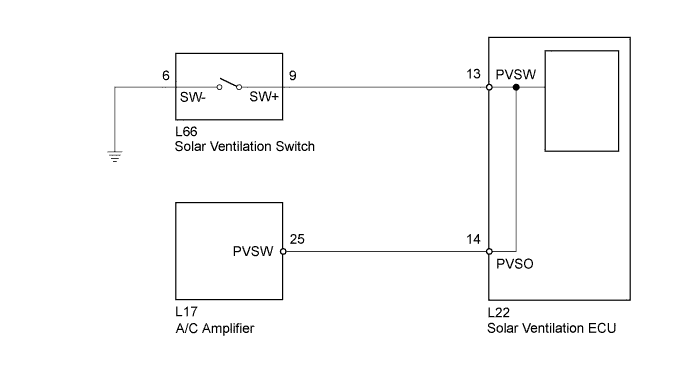
SOLAR VENTILATION SYSTEM > Solar Ventilation Switch Circuit |
| 1.READ VALUE USING TECHSTREAM |
Connect the Techstream to the DLC3.
Turn the power switch on (IG).
Turn the Techstream on.
Enter the following menus: Body Electrical / Air Conditioner / Data List.
Check the value(s) by referring to the table below.
| Tester Display | Measurement Item/Range | Normal Condition | Diagnostic Note |
| Solar Ventilation Switch | Solar ventilation switch (Switch recognition value at A/C amplifier side) / OFF or ON | OFF: Solar ventilation switch off ON: Solar ventilation switch on | - |
| Solar Ventilation Switch Status | Solar ventilation switch (Switch recognition value at solar ventilation ECU side) / OFF or ON | OFF: Solar ventilation switch off ON: Solar ventilation switch on | - |
| Result | Proceed to |
| OK | A |
| NG (OFF/ON display does not change for both Solar Ventilation Switch Status and Solar Ventilation Switch even though the solar ventilation switch is operated.) | B |
| NG (OFF/ON display does not change for Solar Ventilation Switch even though the solar ventilation switch is operated.) | C |
| NG (OFF/ON display does not change for Solar Ventilation Switch Status even though the solar ventilation switch is operated.) | D |
|
| ||||
|
| ||||
|
| ||||
| A | ||
 | ||
| ||
| 2.INSPECT SOLAR VENTILATION SWITCH |
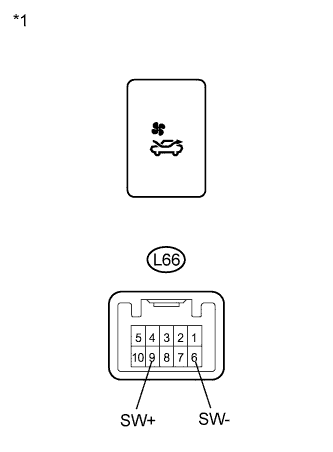 |
Remove the solar ventilation switch.
Measure the resistance according to the value(s) in the table below.
| Tester Connection | Condition | Specified Condition |
| L66-9 (SW+) - L66-6 (SW-) | Solar ventilation switch: off (when switch is not pressed) | 10 kΩ or higher |
| L66-9 (SW+) - L66-6 (SW-) | Solar ventilation switch: on (when switch is pressed) | Below 1 Ω |
| *1 | Component without harness connected (Solar Ventilation Switch) |
|
| ||||
| OK | |
 |
| 3.CHECK HARNESS AND CONNECTOR (SOLAR VENTILATION SWITCH - BODY GROUND) |
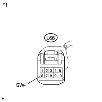 |
Measure the resistance according to the value(s) in the table below.
| Tester Connection | Condition | Specified Condition |
| L66-6 (SW-) - Body ground | Always | Below 1 Ω |
| *1 | Front view of wire harness connector (to Solar Ventilation Switch) |
|
| ||||
| OK | |
|
| 4.CHECK HARNESS AND CONNECTOR (SOLAR VENTILATION SWITCH - SOLAR VENTILATION ECU) |
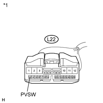 |
Disconnect the solar ventilation ECU connector.
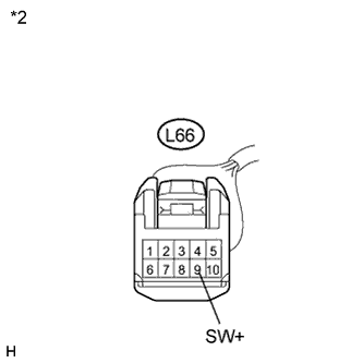 |
Measure the resistance according to the value(s) in the table below.
| Tester Connection | Condition | Specified Condition |
| L22-13 (PVSW) - L66-9 (SW+) | Always | Below 1 Ω |
| L22-13 (PVSW) - Body ground | Always | 10 kΩ or higher |
| *1 | Front view of wire harness connector (to Solar Ventilation ECU) |
| *2 | Front view of wire harness connector (to Solar Ventilation Switch) |
|
| ||||
| OK | ||
| ||
| ||
| 5.CHECK HARNESS AND CONNECTOR (SOLAR VENTILATION ECU - A/C AMPLIFIER) |
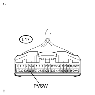 |
Disconnect the A/C amplifier connector.
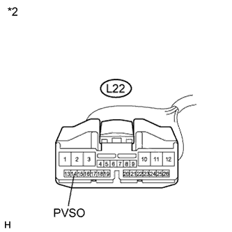 |
Measure the resistance according to the value(s) in the table below.
| Tester Connection | Condition | Specified Condition |
| L17-25 (PVSW) - L22-14 (PVSO) | Always | Below 1 Ω |
| L17-25 (PVSW) - Body ground | Always | 10 kΩ or higher |
| *1 | Front view of wire harness connector (to A/C Amplifier) |
| *2 | Front view of wire harness connector (to Solar Ventilation ECU) |
|
| ||||
| OK | |
|
| 6.REPLACE SOLAR VENTILATION ECU |
Replace the solar ventilation ECU with a known good one and check if the same problem occurs again (Click here).
|
| ||||
| OK | ||
| ||
| ||

