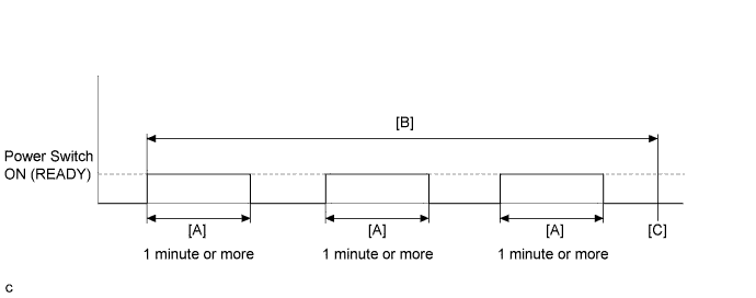
DTC P0A1B-163 Drive Motor "A" Control Module |
DTC P0A1B-164 Drive Motor "A" Control Module |
DTC P0A1B-192 Drive Motor "A" Control Module |
DTC P0A1B-193 Drive Motor "A" Control Module |
DTC P0A1B-511 Drive Motor "A" Control Module |
DTC P0A1B-512 Drive Motor "A" Control Module |
DTC P0A1B-661 Drive Motor "A" Control Module |
DTC P0A1B-786 Drive Motor "A" Control Module |
DTC P0A1B-794 Drive Motor "A" Control Module |
| DTC No. | INF Code | DTC Detection Condition | Trouble Area |
| P0A1B | 163 | MG ECU internal malfunction IPM positive power source error (1 trip detection logic) | Inverter with converter assembly |
| 164 | MG ECU internal malfunction IPM negative power source error (1 trip detection logic) | ||
| 192 | MG ECU internal malfunction A/D converter malfunction (1 trip detection logic) | ||
| 193 | MG ECU internal malfunction CPU ROM-RAM error (1 trip detection logic) | ||
| 511 | MG ECU internal malfunction Standard voltage for analog signal offset (+2.5 V) error (1 trip detection logic) | ||
| 512 | MG ECU internal malfunction Standard voltage for analog signal (+5 V) error (1 trip detection logic) | ||
| 661 | MG ECU internal malfunction Communication error (from motor (MG2) to generator (MG1)) (1 trip detection logic) | ||
| 786 | MG ECU internal malfunction Calculation check error (1 trip detection logic) | ||
| 794 | MG ECU internal malfunction R/D converter communication error (1 trip detection logic) |
| DTC No. | Data List |
| P0A1B-794 | Motor (MG2) Revolution |
| P0A1B-163 P0A1B-164 P0A1B-192 P0A1B-193 P0A1B-511 P0A1B-512 P0A1B-661 P0A1B-786 | - |
| Related DTCs | P0A1B (INF 163): Motor CPU power malfunction (26 V) P0A1B (INF 164): Motor CPU power malfunction (-5 V) P0A1B (INF 192): A/D malfunction (2 MG CPU) P0A1B (INF 193): RAM and ROM destruction P0A1B (INF 511): Motor CPU power malfunction (2.5 V) P0A1B (INF 512): Motor CPU power malfunction (5 VAref) P0A1B (INF 661): MG CPU communication malfunction (2 MG CPU to 1 MG CPU) P0A1B (INF 786): MG CPU ALU malfunction P0A1B (INF 794): R/D converter communication malfunction |
| Required sensors / components | Inverter with converter (MG ECU) |
| Frequency of operation | Continuous |
| Duration | TMC's intellectual property |
| MIL operation | 1 driving cycle |
| Sequence of operation | None |
| The monitor will run whenever the following DTCs are not present | TMC's intellectual property |
| Other conditions belong to TMC's intellectual property | - |
| TMC's intellectual property | - |
| Power management control ECU (HV CPU) | DTC P0A1B (INF 163/164/192/193/511/512/661/786/794) is not detected |
| 1.REPLACE INVERTER WITH CONVERTER ASSEMBLY |
Replace the inverter with converter assembly (Click here).
| NEXT | ||
 | ||
| ||