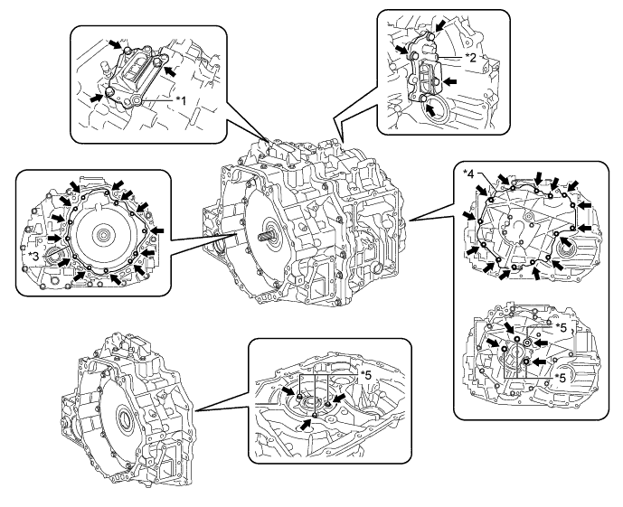
| *1 | Generator Cable Terminal | *2 | Motor Cable Terminal |
| *3 | Transaxle Housing Cover | *4 | Rear Transaxle Case Cover Sub-assembly |
| *5 | Resolver Adjuster Bolt | - | - |
HYBRID VEHICLE TRANSAXLE UNIT > DISASSEMBLY |
| *1 | Generator Cable Terminal | *2 | Motor Cable Terminal |
| *3 | Transaxle Housing Cover | *4 | Rear Transaxle Case Cover Sub-assembly |
| *5 | Resolver Adjuster Bolt | - | - |
| 1. INSPECT INPUT SHAFT END PLAY |
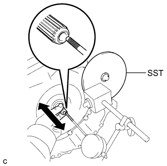 |
Using SST and a dial indicator, measure the input shaft assembly end play.
| 2. REMOVE SHIFT CONTROL ACTUATOR ASSEMBLY |
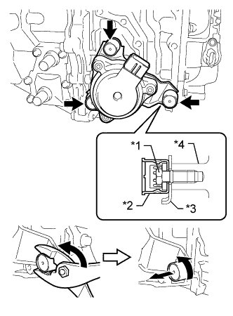 |
Using pliers or an equivalent tool, turn the shift control actuator bolt covers counterclockwise and remove the 3 shift control actuator bolts and shift control actuator assembly.
| *1 | Shift Control Actuator Bolt |
| *2 | Shift Control Actuator Bolt Cover |
| *3 | Shift Control Actuator Assembly |
| *4 | Hybrid Vehicle Transaxle Assembly |
| 3. REMOVE TRANSAXLE BREATHER PLUG |
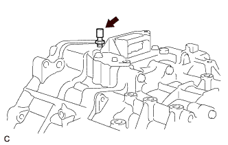 |
Remove the transaxle breather plug from the hybrid vehicle transaxle assembly.
| 4. REMOVE WITH HEAD STRAIGHT SCREW PLUG |
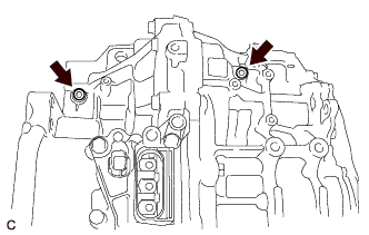 |
Using a 6 mm hexagon socket wrench, remove the 2 with head straight screw plugs from the hybrid vehicle transaxle assembly.
| 5. REMOVE TRANSMISSION OIL PUMP COVER SUB-ASSEMBLY |
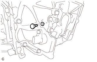 |
Remove the fluid pump cover plug and O-ring from the transmission oil pump cover sub-assembly.
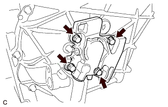 |
Remove the 4 bolts and transmission oil pump cover sub-assembly from the hybrid vehicle transaxle assembly.
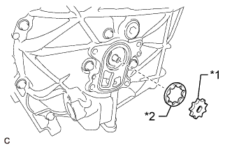 |
Remove the transaxle oil pump drive rotor and transmission oil pump driven rotor from the hybrid vehicle transaxle assembly.
| *1 | Transaxle Oil Pump Drive Rotor |
| *2 | Transmission Oil Pump Driven Rotor |
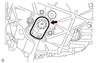 |
Remove the O-ring from the hybrid vehicle transaxle assembly.
| 6. REMOVE OIL PUMP DRIVE SHAFT |
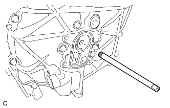 |
Remove the oil pump drive shaft from the hybrid vehicle transaxle assembly.
| 7. SECURE HYBRID VEHICLE TRANSAXLE ASSEMBLY |
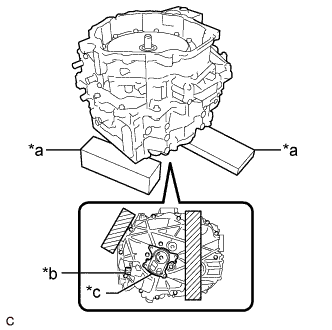 |
Place wooden blocks under the hybrid vehicle transaxle assembly.
| *a | Wooden Block |
| *b | Resolver Sensor Connector |
| *c | Installation area of the transmission oil pump cover sub-assembly |
 | Wooden block placement position |
| 8. REMOVE FILLER PLUG |
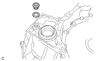 |
Using a 10 mm hexagon socket wrench, remove the filler plug and gasket from the hybrid vehicle transaxle assembly.
| 9. REMOVE DRAIN PLUG |
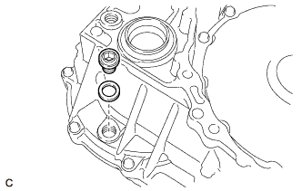 |
Using a 10 mm hexagon socket wrench, remove the drain plug and gasket from the hybrid vehicle transaxle assembly.
| 10. REMOVE NO. 1 MOTOR WATER JACKET COVER ASSEMBLY |
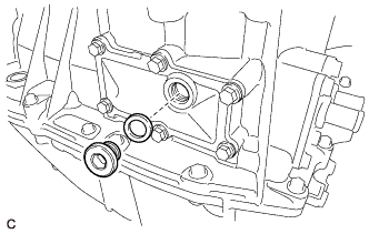 |
Using a 10 mm hexagon socket wrench, remove the drain plug and gasket from the No. 1 motor water jacket cover assembly.
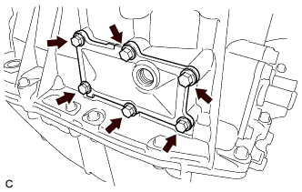 |
Remove the 6 bolts from the No. 1 motor water jacket cover assembly.
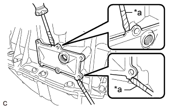 |
Using a screwdriver, remove the No. 1 motor water jacket cover assembly from the hybrid vehicle transaxle assembly.
| *a | Protective Tape |
| 11. REMOVE NO. 2 MOTOR WATER JACKET COVER ASSEMBLY |
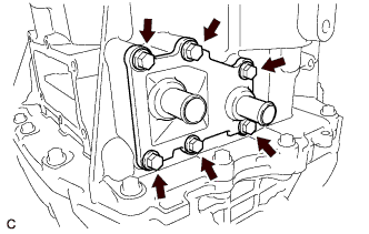 |
Remove the 6 bolts from the No. 2 motor water jacket cover assembly.
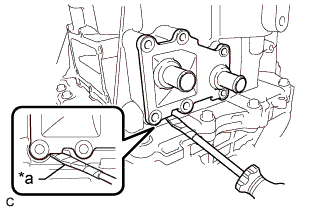 |
Using a screwdriver, remove the No. 2 motor water jacket cover assembly from the hybrid vehicle transaxle assembly.
| *a | Protective Tape |
| 12. REMOVE HYBRID VEHICLE GENERATOR ASSEMBLY |
Install the No. 1 engine hanger and No. 2 engine hanger with the 2 bolts and washer as shown in the illustration.
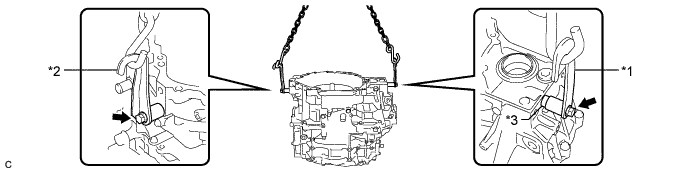
| *1 | No. 1 Engine Hanger | *2 | No. 2 Engine Hanger |
| *3 | Washer | - | - |
| Part Name | Part No. |
| No. 1 Engine Hanger | 12281-37050 |
| No. 2 Engine Hanger | 12282-37040 |
| Bolt | 91552-81050 |
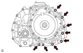 |
Remove the 8 bolts from the hybrid vehicle generator assembly.
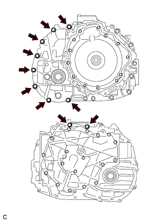 |
Remove the 8 bolts from the hybrid vehicle generator assembly.
Remove the 2 bolts from the hybrid vehicle motor assembly.
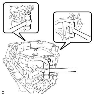 |
While lifting the hybrid vehicle generator assembly with a chain, tap the areas shown in the illustration with a plastic hammer and separate the hybrid vehicle generator assembly from the hybrid vehicle motor assembly.
While lifting the hybrid vehicle generator assembly with a chain, remove it from the hybrid vehicle motor assembly.
Remove the 2 bolts, washer, No. 1 engine hanger and No. 2 engine hanger from the hybrid vehicle generator assembly.
| 13. REMOVE TRANSAXLE HOUSING OIL SEPARATOR |
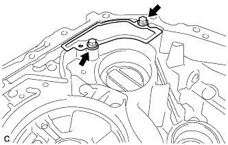 |
Remove the 2 bolts and transaxle housing oil separator from the hybrid vehicle generator assembly.
| 14. REMOVE HYBRID VEHICLE TRANSAXLE ASSEMBLY TYPE T OIL SEAL (RH SIDE) |
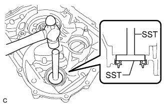 |
Using SST and a hammer, remove the hybrid vehicle transaxle assembly type T oil seal (RH side) from the hybrid vehicle generator assembly.
| 15. REMOVE TAPERED ROLLER BEARING (RH SIDE OUTER RACE) |
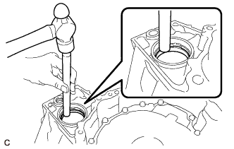 |
Using a brass bar and a hammer, remove the tapered roller bearing (RH side outer race) and differential case RH shim from the hybrid vehicle generator assembly.
| 16. REMOVE INPUT SHAFT TYPE T OIL SEAL |
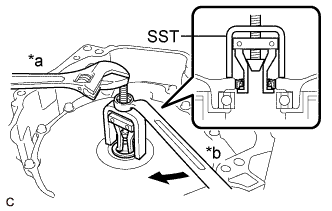 |
Using SST, remove the input shaft type T oil seal from the hybrid vehicle generator assembly.
| *a | Hold |
| *b | Turn |
| 17. REMOVE COUNTER DRIVEN GEAR SHIM |
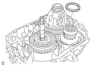 |
Remove the counter driven gear shim from the counter driven gear sub-assembly.
| 18. REMOVE PARKING LOCK PAWL |
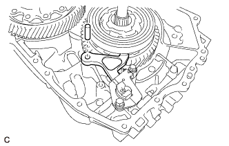 |
Remove the parking lock pawl and parking lock pawl shaft from the hybrid vehicle motor assembly.
| 19. REMOVE PAWL STOPPER PLATE |
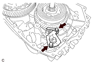 |
Remove the 2 bolts and pawl stopper plate from the hybrid vehicle motor assembly.
| 20. REMOVE TORSION SPRING |
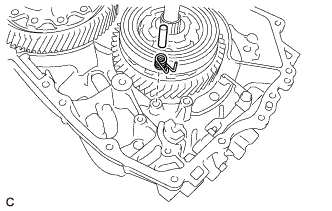 |
Remove the parking lock pawl shaft and torsion spring from the hybrid vehicle motor assembly.
| 21. REMOVE PARKING LOCK SLEEVE |
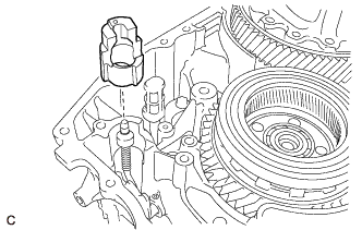 |
Remove the parking lock sleeve from the hybrid vehicle motor assembly.
| 22. REMOVE MANUAL DETENT SPRING SUB-ASSEMBLY |
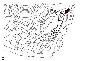 |
Remove the bolt and manual detent spring sub-assembly from the hybrid vehicle motor assembly.
| 23. REMOVE RETAINER SPRING |
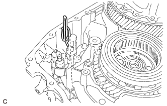 |
Remove the retainer spring from the hybrid vehicle motor assembly and No. 1 parking lock shaft.
| 24. REMOVE NO. 1 PARKING LOCK SHAFT |
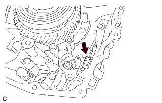 |
Using a hammer and a screwdriver, cut off the spacer and remove it from the No. 1 parking lock shaft.
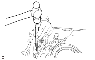 |
Using a 5 mm pin punch and a hammer, drive out the slotted spring pin from the No. 1 parking lock shaft.
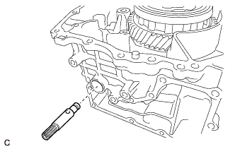 |
Remove the No. 1 parking lock shaft from the hybrid vehicle motor assembly.
| 25. REMOVE PARKING LOCK ROD SUB-ASSEMBLY |
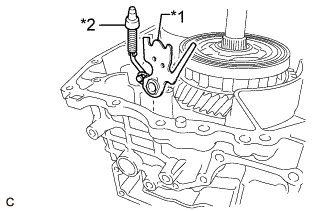 |
Remove the No. 1 parking lock lever sub-assembly and parking lock rod sub-assembly from the hybrid vehicle motor assembly.
| *1 | No. 1 Parking Lock Lever Sub-assembly |
| *2 | Parking Lock Rod Sub-assembly |
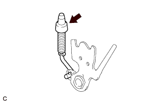 |
Remove the parking lock rod sub-assembly from the No. 1 parking lock lever sub-assembly.
| 26. REMOVE NO. 1 TRANSMISSION MAGNET |
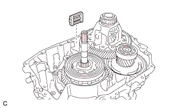 |
Remove the No. 1 transmission magnet from the hybrid vehicle motor assembly.
| 27. REMOVE INPUT SHAFT ASSEMBLY |
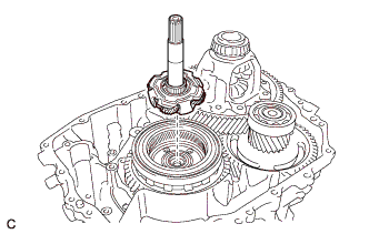 |
Remove the input shaft assembly from the counter drive gear sub-assembly.
| 28. REMOVE PLANETARY SUN GEAR |
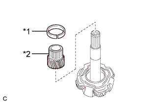 |
Remove the planetary sun gear snap ring and planetary sun gear from the input shaft assembly.
| *1 | Planetary Sun Gear Snap Ring |
| *2 | Planetary Sun Gear |
| 29. REMOVE THRUST NEEDLE ROLLER BEARING |
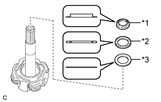 |
Remove the thrust bearing race, thrust needle roller bearing and No. 1 thrust bearing race from the input shaft assembly.
| *1 | Thrust Bearing Race |
| *2 | Thrust Needle Roller Bearing |
| *3 | No. 1 Thrust Bearing Race |
| 30. REMOVE DIFFERENTIAL CASE SUB-ASSEMBLY |
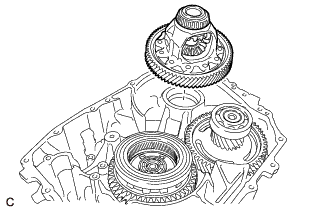 |
Remove the differential case sub-assembly from the hybrid vehicle motor assembly.
| 31. REMOVE COUNTER DRIVEN GEAR SUB-ASSEMBLY |
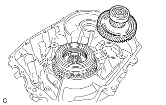 |
Remove the counter driven gear sub-assembly from the hybrid vehicle motor assembly.
| 32. REMOVE COUNTER DRIVE GEAR SUB-ASSEMBLY |
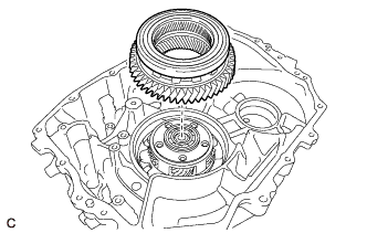 |
Remove the counter drive gear sub-assembly from the No. 1 rear planetary gear assembly.
| 33. REMOVE NO. 1 REAR PLANETARY GEAR ASSEMBLY |
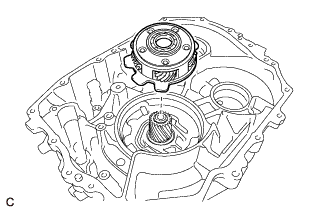 |
Remove the No. 1 rear planetary gear assembly from the rear planetary sun gear.
| 34. INSPECT NO. 1 REAR PLANETARY GEAR ASSEMBLY |
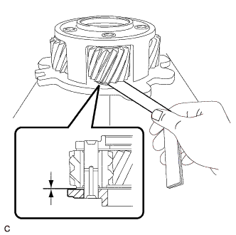 |
Using a feeler gauge, measure the clearance between the No. 1 rear planetary gear assembly and the pinion gear.
| 35. REMOVE REAR PLANETARY SUN GEAR |
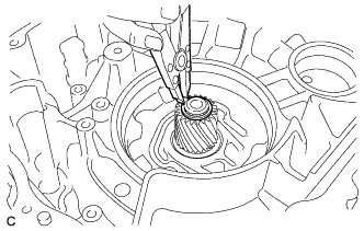 |
Using a snap ring expander, remove the rear planetary sun gear shaft snap ring from the hybrid vehicle motor assembly.
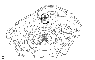 |
Remove the rear planetary sun gear from the hybrid vehicle motor assembly.
| 36. REMOVE TRANSMISSION OIL STRAINER |
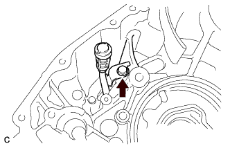 |
Remove the bolt and transmission oil strainer from the hybrid vehicle motor assembly.
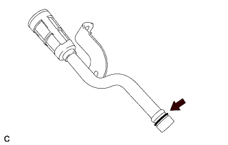 |
Remove the O-ring from the transmission oil strainer.
| 37. REMOVE HYBRID VEHICLE TRANSAXLE ASSEMBLY TYPE T OIL SEAL (LH SIDE) |
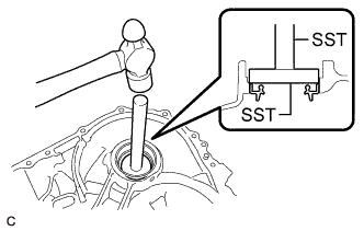 |
Using SST and a hammer, remove the hybrid vehicle transaxle assembly type T oil seal (LH side) from the hybrid vehicle motor assembly.
| 38. REMOVE TAPERED ROLLER BEARING (LH SIDE OUTER RACE) |
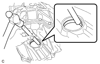 |
Using a brass bar and a hammer, remove the tapered roller bearing (LH side outer race) from the hybrid vehicle motor assembly.
| 39. REMOVE SHIFT CONTROL ACTUATOR SEAL |
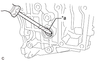 |
Using a screwdriver, remove the shift control actuator seal from the hybrid vehicle motor assembly.
| *a | Protective Tape |
| 40. REMOVE TAPERED ROLLER BEARING (RH SIDE INNER RACE) |
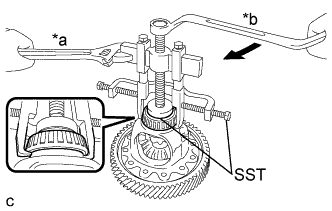 |
Using SST, remove the tapered roller bearing (RH side inner race) from the differential case sub-assembly.
| *a | Hold |
| *b | Turn |
| 41. REMOVE TAPERED ROLLER BEARING (LH SIDE INNER RACE) |
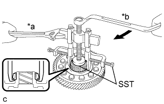 |
Using SST, remove the tapered roller bearing (LH side inner race) from the differential case sub-assembly.
| *a | Hold |
| *b | Turn |
| 42. REMOVE RADIAL BALL BEARING (LH SIDE) |
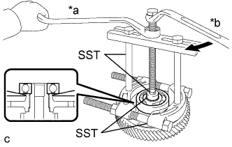 |
Using SST, remove the radial ball bearing (LH side) from the counter driven gear sub-assembly.
| *a | Hold |
| *b | Turn |
| 43. REMOVE RADIAL BALL BEARING (RH SIDE) |
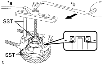 |
Using SST, remove the radial ball bearing (RH side) from the counter driven gear sub-assembly.
| *a | Hold |
| *b | Turn |
| 44. REMOVE STRAIGHT PIN |
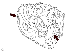 |
Remove the 2 straight pins from the hybrid vehicle motor assembly.