 |
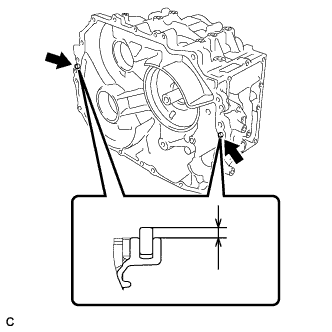
Using a plastic hammer, install the 2 straight pins to the hybrid vehicle motor assembly.
- Standard Protrusion:
- 7.0 to 8.5 mm (0.276 to 0.335 in.)
HYBRID VEHICLE TRANSAXLE UNIT > REASSEMBLY |
| 1. INSTALL STRAIGHT PIN |
|
Using a plastic hammer, install the 2 straight pins to the hybrid vehicle motor assembly.
| 2. INSTALL RADIAL BALL BEARING (LH SIDE) |
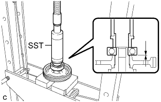 |
Using SST and a press, install the radial ball bearing (LH side) to the counter driven gear sub-assembly.
| 3. INSTALL RADIAL BALL BEARING (RH SIDE) |
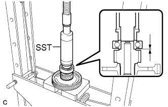 |
Using SST and a press, install the radial ball bearing (RH side) to the counter driven gear sub-assembly.
| 4. INSTALL TAPERED ROLLER BEARING (LH SIDE INNER RACE) |
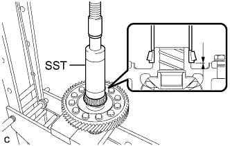 |
Using SST and a press, install the tapered roller bearing (LH side inner race) to the differential case sub-assembly.
| 5. INSTALL TAPERED ROLLER BEARING (RH SIDE INNER RACE) |
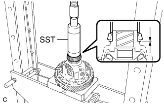 |
Using SST and a press, install the tapered roller bearing (RH side inner race) to the differential case sub-assembly.
| 6. INSTALL TAPERED ROLLER BEARING (LH SIDE OUTER RACE) |
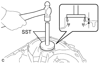 |
Using SST and a hammer, install the tapered roller bearing (LH side outer race) to the hybrid vehicle motor assembly.
| 7. INSTALL TAPERED ROLLER BEARING (RH SIDE OUTER RACE) |
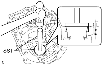 |
Using SST and a hammer, install the tapered roller bearing (RH side outer race) and differential case RH shim to the hybrid vehicle generator assembly.
| 8. ADJUST PRELOAD |
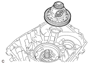 |
Install the differential case sub-assembly to the hybrid vehicle motor assembly.
Install the No. 1 engine hanger and No. 2 engine hanger with the 2 bolts and washer as shown in the illustration.
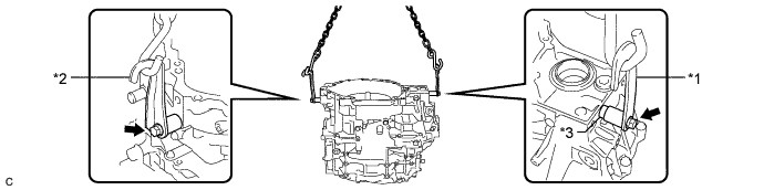
| *1 | No. 1 Engine Hanger | *2 | No. 2 Engine Hanger |
| *3 | Washer | - | - |
| Part Name | Part No. |
| No. 1 Engine Hanger | 12281-37050 |
| No. 2 Engine Hanger | 12282-37040 |
| Bolt | 91552-81050 |
Using the sling device and chain block, install the hybrid vehicle generator assembly to the hybrid vehicle motor assembly.
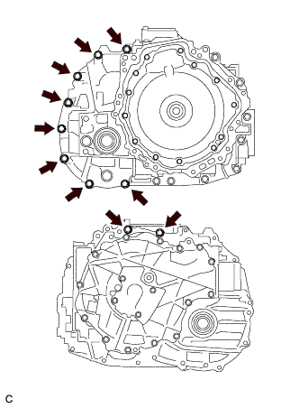 |
Install the 8 bolts to the hybrid vehicle generator assembly.
Install the 2 bolts to the hybrid vehicle motor assembly.
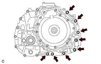 |
Install the 8 bolts to the hybrid vehicle generator assembly.
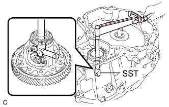 |
Using SST and a torque wrench, measure the starting torque and turning torque of the differential case sub-assembly.
| Starting Torque | New tapered roller bearing | 1.3 to 2.9 N*m (13 to 30 kgf*cm, 12 to 26 in.*lbf) |
| Reused tapered roller bearing | 0.9 to 2.3 N*m (9 to 23 kgf*cm, 8 to 20 in.*lbf) | |
| Turning Torque (20 rpm) | New tapered roller bearing | 0.8 to 1.5 N*m (8 to 15 kgf*cm, 7 to 13 in.*lbf) |
| Reused tapered roller bearing | 0.5 to 0.8 N*m (5 to 8 kgf*cm, 4 to 7 in.*lbf) |
| Part No. | Thickness (mm (in.)) | Part No. | Thickness (mm (in.)) |
| 90564-64031 | 1.70 (0.0669) | 90564-64039 | 2.10 (0.0827) |
| 90564-64047 | 1.725 (0.0679) | 90564-64055 | 2.125 (0.0837) |
| 90564-64032 | 1.75 (0.0689) | 90564-64040 | 2.15 (0.0846) |
| 90564-64048 | 1.775 (0.0699) | 90564-64056 | 2.175 (0.0856) |
| 90564-64033 | 1.80 (0.0709) | 90564-64041 | 2.20 (0.0866) |
| 90564-64049 | 1.825 (0.0719) | 90564-64057 | 2.225 (0.0876) |
| 90564-64034 | 1.85 (0.0728) | 90564-64042 | 2.25 (0.0886) |
| 90564-64050 | 1.875 (0.0738) | 90564-64058 | 2.275 (0.0896) |
| 90564-64035 | 1.90 (0.0748) | 90564-64043 | 2.30 (0.0906) |
| 90564-64051 | 1.925 (0.0758) | 90564-64059 | 2.325 (0.0915) |
| 90564-64036 | 1.95 (0.0768) | 90564-64044 | 2.35 (0.0925) |
| 90564-64052 | 1.975 (0.0778) | 90564-64060 | 2.375 (0.0935) |
| 90564-64037 | 2.00 (0.0787) | 90564-64045 | 2.40 (0.0945) |
| 90564-64053 | 2.025 (0.0797) | 90564-64061 | 2.425 (0.0955) |
| 90564-64038 | 2.05 (0.0807) | 90564-64046 | 2.45 (0.0965) |
| 90564-64054 | 2.075 (0.0817) | - | - |
Remove the 18 bolts from the hybrid vehicle motor assembly and hybrid vehicle generator assembly.
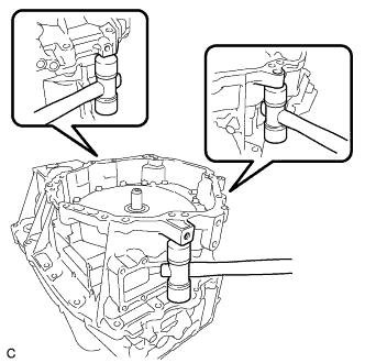 |
While lifting the hybrid vehicle generator assembly with a chain, tap the areas shown in the illustration with a plastic hammer and separate the hybrid vehicle generator assembly from the hybrid vehicle motor assembly.
While lifting the hybrid vehicle generator assembly with a chain, remove it from the hybrid vehicle motor assembly.
Remove the differential case sub-assembly from the hybrid vehicle motor assembly.
Remove the 2 bolts, washer, No. 1 engine hanger and No. 2 engine hanger from the hybrid vehicle generator assembly.
| 9. INSTALL SHIFT CONTROL ACTUATOR SEAL |
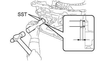 |
Using SST and a hammer, install a new shift control actuator seal to the hybrid vehicle motor assembly.
Coat the lip of the shift control actuator seal with a small amount of MP grease.
| 10. INSTALL HYBRID VEHICLE TRANSAXLE ASSEMBLY TYPE T OIL SEAL (LH SIDE) |
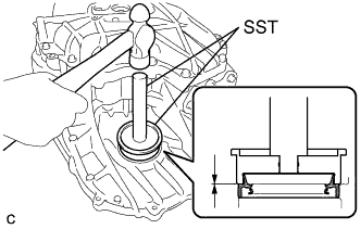 |
Using SST and a hammer, install a new hybrid vehicle transaxle assembly type T oil seal (LH side) to the hybrid vehicle motor assembly.
Coat the lip of the hybrid vehicle transaxle assembly type T oil seal (LH side) with a small amount of MP grease.
| 11. INSTALL TRANSMISSION OIL STRAINER |
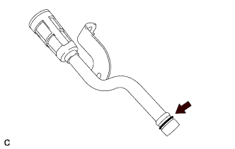 |
Coat a new O-ring with ATF and install it to the transmission oil strainer.
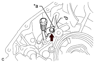 |
Install the transmission oil strainer to the hybrid vehicle motor assembly with the bolt.
| *a | Detent |
| *b | Rib |
| 12. INSTALL REAR PLANETARY SUN GEAR |
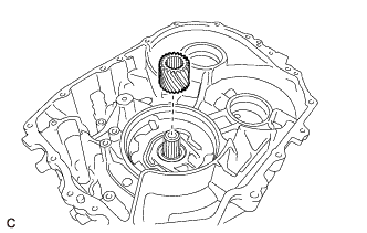 |
Install the rear planetary sun gear to the hybrid vehicle motor assembly.
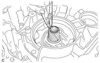 |
Using a snap ring expander, install a new rear planetary sun gear shaft snap ring to the hybrid vehicle motor assembly.
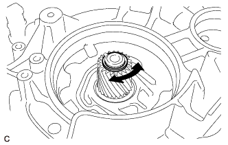 |
Turn the rear planetary sun gear shaft snap ring and check that it is not loose.
| 13. INSTALL NO. 1 REAR PLANETARY GEAR ASSEMBLY |
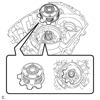 |
Install the No. 1 rear planetary gear assembly to the rear planetary sun gear.
| 14. INSTALL COUNTER DRIVE GEAR SUB-ASSEMBLY |
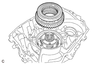 |
Install the counter drive gear sub-assembly to the No. 1 rear planetary gear assembly.
| 15. INSTALL COUNTER DRIVEN GEAR SUB-ASSEMBLY |
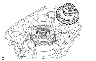 |
Install the counter driven gear sub-assembly to the hybrid vehicle motor assembly.
| 16. INSTALL DIFFERENTIAL CASE SUB-ASSEMBLY |
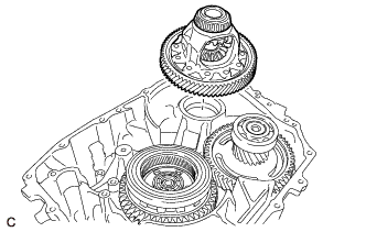 |
Install the differential case sub-assembly to the hybrid vehicle motor assembly.
| 17. INSTALL THRUST NEEDLE ROLLER BEARING |
Apply ATF to the contact surfaces of the thrust needle roller bearing.
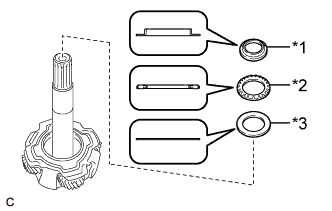 |
Install the No. 1 thrust bearing race, thrust needle roller bearing and thrust bearing race to the input shaft assembly.
| *1 | Thrust Bearing Race |
| *2 | Thrust Needle Roller Bearing |
| *3 | No. 1 Thrust Bearing Race |
| 18. INSTALL INPUT SHAFT ASSEMBLY |
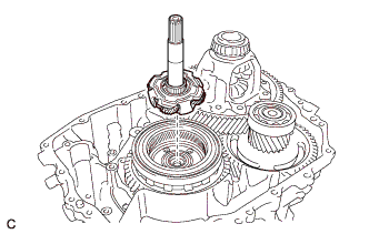 |
Install the input shaft assembly to the counter drive gear sub-assembly.
| 19. INSTALL PLANETARY SUN GEAR |
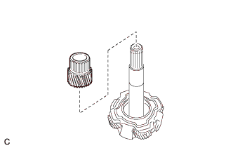 |
Install the planetary sun gear to the input shaft assembly.
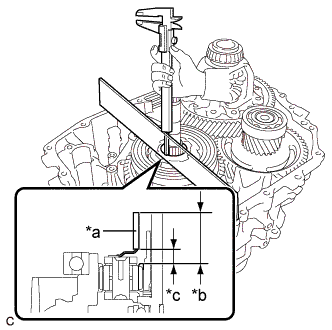
Select a planetary sun gear snap ring.
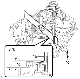 |
Using a straightedge and vernier caliper, measure dimension A shown in the illustration.
| *a | Straightedge |
| *b | Measured Area |
| *c | Dimension A |
 |
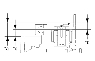
Using a straightedge and vernier caliper, measure dimension B shown in the illustration.
| *a | Straightedge |
| *b | Measured Area |
| *c | Dimension B |
 |
Calculate dimension C.
| *a | Dimension A |
| *b | Dimension B |
| *c | Dimension C |
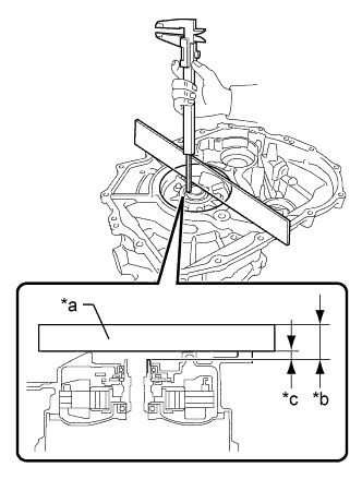 |
Using a straightedge and vernier caliper, measure dimension D shown in the illustration.
| *a | Straightedge |
| *b | Measured Area |
| *c | Dimension D |
Select a planetary sun gear snap ring.
| Part No. | Thickness (mm (in.)) | Part No. | Thickness (mm (in.)) |
| 90520-31035 | 3.88 (0.153) | 90520-31050 | 4.33 (0.170) |
| 90520-31036 | 3.91 (0.154) | 90520-31051 | 4.36 (0.172) |
| 90520-31037 | 3.94 (0.155) | 90520-31052 | 4.39 (0.173) |
| 90520-31038 | 3.97 (0.156) | 90520-31053 | 4.42 (0.174) |
| 90520-31039 | 4.00 (0.157) | 90520-31054 | 4.45 (0.175) |
| 90520-31040 | 4.03 (0.159) | 90520-31055 | 4.48 (0.176) |
| 90520-31041 | 4.06 (0.160) | 90520-31056 | 4.51 (0.178) |
| 90520-31042 | 4.09 (0.161) | 90520-31057 | 4.54 (0.179) |
| 90520-31043 | 4.12 (0.162) | 90520-31058 | 4.57 (0.180) |
| 90520-31044 | 4.15 (0.163) | 90520-31059 | 4.60 (0.181) |
| 90520-31045 | 4.18 (0.165) | 90520-31060 | 4.63 (0.182) |
| 90520-31046 | 4.21 (0.166) | 90520-31061 | 4.66 (0.183) |
| 90520-31047 | 4.24 (0.167) | 90520-31062 | 4.69 (0.185) |
| 90520-31048 | 4.27 (0.168) | 90520-31063 | 4.72 (0.186) |
| 90520-31049 | 4.30 (0.169) | - | - |
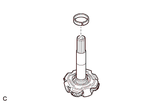 |
Install the planetary sun gear snap ring to the input shaft assembly.
| 20. INSTALL COUNTER DRIVEN GEAR SHIM |
Select a counter driven gear shim.
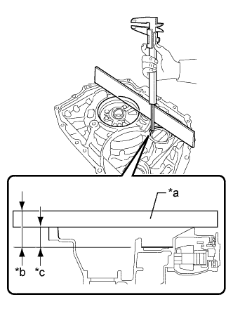 |
Using a straightedge and vernier caliper, measure dimension A shown in the illustration.
| *a | Straightedge |
| *b | Measured Area |
| *c | Dimension A |
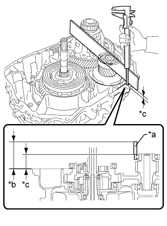 |
Using a straightedge and vernier caliper, measure dimension B shown in the illustration.
| *a | Straightedge |
| *b | Measured Area |
| *c | Dimension B |
Select a counter driven gear shim.
| Part No. | Thickness (mm (in.)) | Part No. | Thickness (mm (in.)) |
| 90564-50281 | 2.00 (0.0787) | 90564-50288 | 2.35 (0.0925) |
| 90564-50282 | 2.05 (0.0807) | 90564-50289 | 2.40 (0.0945) |
| 90564-50283 | 2.10 (0.0827) | 90564-50290 | 2.45 (0.0965) |
| 90564-50284 | 2.15 (0.0846) | 90564-50291 | 2.50 (0.0984) |
| 90564-50285 | 2.20 (0.0866) | 90564-50292 | 2.55 (0.100) |
| 90564-50286 | 2.25 (0.0886) | 90564-50293 | 2.60 (0.102) |
| 90564-50287 | 2.30 (0.0906) | - | - |
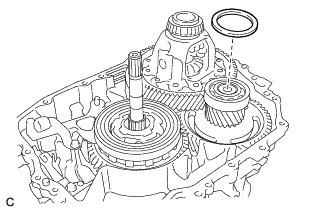 |
Install the counter driven gear shim to the counter driven gear sub-assembly.
| 21. INSTALL NO. 1 TRANSMISSION MAGNET |
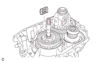 |
Install the No. 1 transmission magnet to the hybrid vehicle motor assembly.
| 22. INSTALL PARKING LOCK ROD SUB-ASSEMBLY |
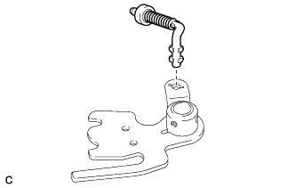 |
Align the slot with the protrusions on the No. 1 parking lock lever sub-assembly and install the parking lock rod sub-assembly.
| 23. INSTALL NO. 1 PARKING LOCK SHAFT |
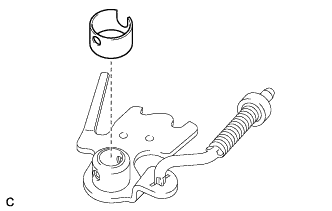 |
Install a new spacer to the No. 1 parking lock lever sub-assembly.
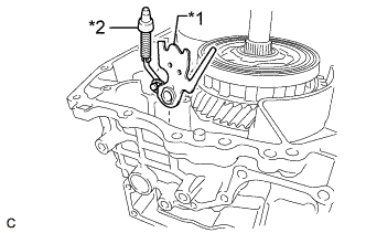 |
Install the No. 1 parking lock lever sub-assembly and parking lock rod sub-assembly to the hybrid vehicle motor assembly.
| *1 | No. 1 Parking Lock Lever Sub-assembly |
| *2 | Parking Lock Rod Sub-assembly |
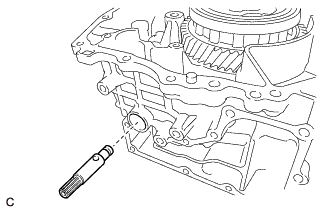 |
Install the No. 1 parking lock shaft to the hybrid vehicle motor assembly.
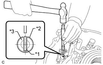 |
Using a 5 mm pin punch and hammer, drive in a new slotted spring pin to the No. 1 parking lock shaft.
| *1 | Slotted Spring Pin |
| *2 | Spacer |
| *3 | No. 1 Parking Lock Shaft |
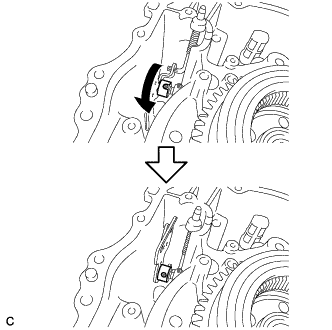 |
Turn the spacer as shown in the illustration.
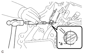 |
Using a 3 mm pin punch and hammer, stake the spacer.
| *a | Stake Point |
| 24. INSTALL RETAINER SPRING |
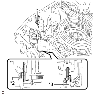 |
Install the retainer spring to the hybrid vehicle motor assembly and No. 1 parking lock shaft.
| *1 | Retainer Spring |
| *2 | No. 1 Parking Lock Shaft |
| *3 | Hybrid Vehicle Motor Assembly |
| 25. INSTALL MANUAL DETENT SPRING SUB-ASSEMBLY |
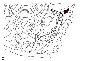 |
Install the manual detent spring sub-assembly to the hybrid vehicle motor assembly with the bolt.
| 26. INSTALL PARKING LOCK SLEEVE |
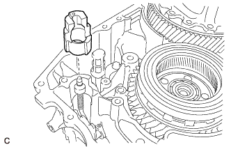 |
Install the parking lock sleeve to the hybrid vehicle motor assembly.
| 27. INSTALL TORSION SPRING |
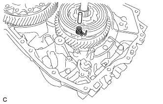 |
Install the parking lock pawl shaft and torsion spring to the hybrid vehicle motor assembly.
| 28. INSTALL PAWL STOPPER PLATE |
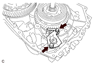 |
Install the pawl stopper plate to the hybrid vehicle motor assembly with the 2 bolts.
| 29. INSTALL PARKING LOCK PAWL |
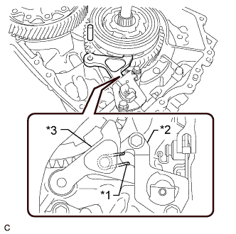 |
Install the parking lock pawl to the hybrid vehicle motor assembly with the parking lock pawl shaft.
| *1 | Torsion Spring |
| *2 | Pawl Stopper Plate |
| *3 | Parking Lock Pawl |
| 30. INSTALL INPUT SHAFT TYPE T OIL SEAL |
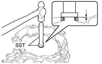 |
Using SST and a hammer, install a new input shaft type T oil seal to the hybrid vehicle generator assembly.
Coat the lip of the input shaft type T oil seal with a small amount of MP grease.
| 31. INSTALL HYBRID VEHICLE TRANSAXLE ASSEMBLY TYPE T OIL SEAL (RH SIDE) |
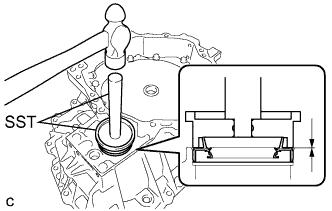 |
Using SST and a hammer, install a new hybrid vehicle transaxle assembly type T oil seal (RH side) to the hybrid vehicle generator assembly.
Coat the lip of the hybrid vehicle transaxle assembly type T oil seal (RH side) with a small amount of MP grease.
| 32. INSTALL TRANSAXLE HOUSING OIL SEPARATOR |
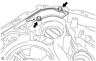 |
Install the transaxle housing oil separator to the hybrid vehicle generator assembly with the 2 bolts.
| 33. INSTALL HYBRID VEHICLE GENERATOR ASSEMBLY |
Clean the hybrid vehicle motor assembly installation surface of the hybrid vehicle generator assembly.
Clean the hybrid vehicle generator assembly installation surface of the hybrid vehicle motor assembly.
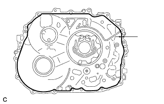 |
Apply seal packing to the hybrid vehicle motor assembly as shown in the illustration.
 | Seal Packing |
Install the No. 1 engine hanger and No. 2 engine hanger with the 2 bolts and washer as shown in the illustration.
| *1 | No. 1 Engine Hanger | *2 | No. 2 Engine Hanger |
| *3 | Washer | - | - |
| Part Name | Part No. |
| No. 1 Engine Hanger | 12281-37050 |
| No. 2 Engine Hanger | 12282-37040 |
| Bolt | 91552-81050 |
Using the sling device and chain block, install the hybrid vehicle generator assembly to the hybrid vehicle motor assembly.
Remove the 2 bolts, washer, No. 1 engine hanger and No. 2 engine hanger from the hybrid vehicle generator assembly.
|
Install the 8 bolts to the hybrid vehicle generator assembly.
Install the 2 bolts to the hybrid vehicle motor assembly.
|
Install the 8 bolts to the hybrid vehicle generator assembly.
| 34. INSTALL NO. 2 MOTOR WATER JACKET COVER ASSEMBLY |
Clean the No. 2 motor water jacket cover assembly installation surface of the hybrid vehicle transaxle assembly.
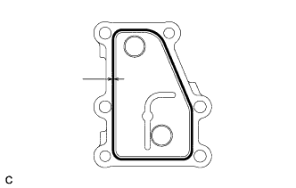 |
Apply seal packing to the No. 2 motor water jacket cover assembly as shown in the illustration.
| Seal Packing |
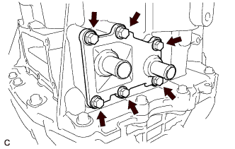 |
Install the No. 2 motor water jacket cover assembly to the hybrid vehicle transaxle assembly with the 6 bolts.
| 35. INSTALL NO. 1 MOTOR WATER JACKET COVER ASSEMBLY |
Clean the No. 1 motor water jacket cover assembly installation surface of the hybrid vehicle transaxle assembly.
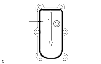 |
Apply seal packing to the No. 1 motor water jacket cover assembly as shown in the illustration.
| Seal Packing |
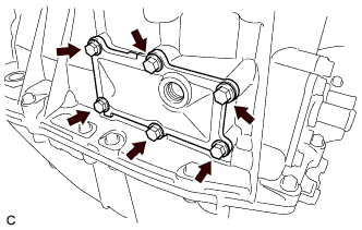 |
Install the No. 1 motor water jacket cover assembly to the hybrid vehicle transaxle assembly with the 6 bolts.
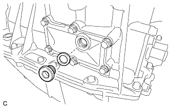 |
Using a 10 mm hexagon socket wrench, install the drain plug and a new gasket to the No. 1 motor water jacket cover assembly.
| 36. INSTALL DRAIN PLUG |
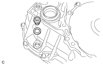 |
Using a 10 mm hexagon socket wrench, install the drain plug and a new gasket to the hybrid vehicle transaxle assembly.
| 37. INSTALL FILLER PLUG |
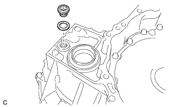 |
Using a 10 mm hexagon socket wrench, install the filler plug and a new gasket to the hybrid vehicle transaxle assembly.
| 38. INSTALL OIL PUMP DRIVE SHAFT |
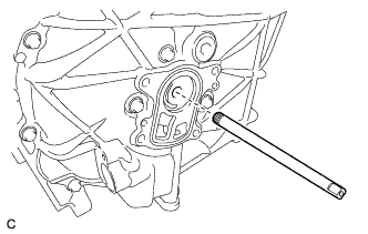 |
Install the oil pump drive shaft to the hybrid vehicle transaxle assembly.
| 39. INSTALL TRANSMISSION OIL PUMP COVER SUB-ASSEMBLY |
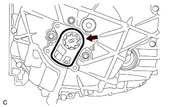 |
Coat a new O-ring with ATF and install it to the hybrid vehicle transaxle assembly.
Apply ATF to the transaxle oil pump drive rotor and transmission oil pump driven rotor.
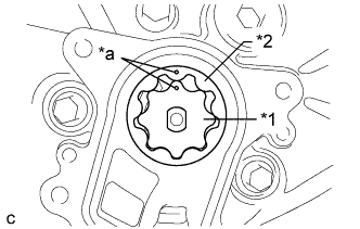 |
Install the transaxle oil pump drive rotor and transmission oil pump driven rotor to the hybrid vehicle transaxle assembly.
| *1 | Transaxle Oil Pump Drive Rotor |
| *2 | Transmission Oil Pump Driven Rotor |
| *a | Matchmark |
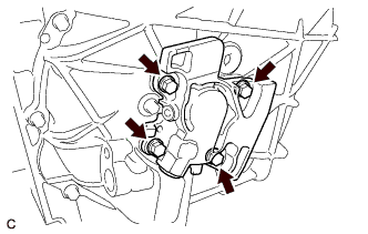 |
Install the transmission oil pump cover sub-assembly to the hybrid vehicle transaxle assembly with the 4 bolts.
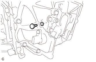 |
Coat a new O-ring with ATF and install it to the fluid pump cover plug.
Install the fluid pump cover plug to the transmission oil pump cover sub-assembly.
| 40. INSTALL WITH HEAD STRAIGHT SCREW PLUG |
Clean and degrease the bolt holes.
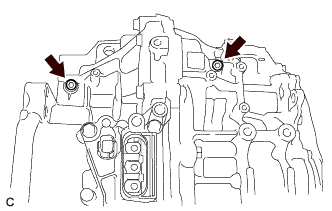 |
Using a 6 mm hexagon socket wrench, install 2 new with head straight screw plugs to the hybrid vehicle transaxle assembly.
| 41. INSTALL TRANSAXLE BREATHER PLUG |
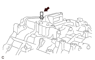 |
Using a union nut wrench, install the transaxle breather plug to the hybrid vehicle transaxle assembly.
| 42. INSTALL SHIFT CONTROL ACTUATOR ASSEMBLY |
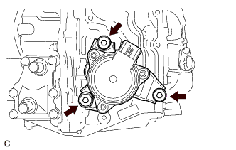 |
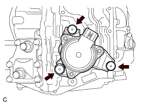
Install the shift control actuator assembly to the hybrid vehicle transaxle assembly with 3 new shift control actuator bolts.
 |
Install 3 new shift control actuator bolt caps to the shift control actuator bolts.
| 43. INSPECT PARKING LOCK |
Turn the power switch on (IG).*1
Depress the brake pedal and release the parking brake.*2
Check that park (P) is selected.*3
Push the vehicle forward by hand and check that it moves slightly and stops.*4
Move the shift lever to neutral (N).*5
Push the vehicle forward by hand and check that it moves.*6
Press the P position switch and check that park (P) is selected.*7
Push the vehicle forward by hand and check that it moves slightly and stops.*8
Perform steps *3 to *8 again, pushing the vehicle rearward this time.