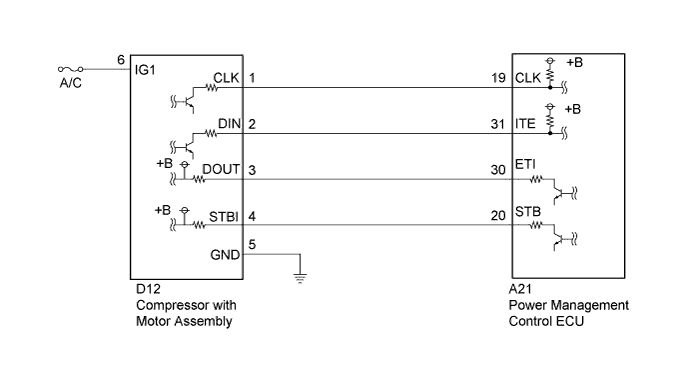
DTC P3108-536 Lost Communication with A/C System Control Module |
| DTC No. | INF Code | DTC Detection Condition | Trouble Area |
| P3108 | 536 | Communication error (air conditioning system to hybrid control system). Error in communication data from the A/C inverter. Although an air conditioning inverter shutdown signal is sent, the air conditioning inverter does not shutdown. (1 trip detection logic) |
|
| DTC No. | Data List |
| P3108-536 |
|
| 1.CHECK DTC OUTPUT (AIR CONDITIONER) |
Connect the Techstream to the DLC3.
Turn the power switch on (READY).
Enter the following menus: Body Electrical / Air Conditioner / Trouble Codes.
Check if DTCs related to the air conditioning system (A/C) are output.
| Result | Proceed to |
| DTCs related to A/C are not output. | A |
| DTCs related to A/C are output. | B |
Turn the power switch off.
|
| ||||
| A | |
 |
| 2.CHECK CONNECTOR CONNECTION CONDITION (POWER MANAGEMENT CONTROL ECU CONNECTOR) |
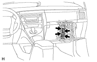 |
Check the connections of the power management control ECU connectors.
|
| ||||
| OK | |
|
| 3.CHECK CONNECTOR CONNECTION CONDITION (COMPRESSOR WITH MOTOR ASSEMBLY CONNECTOR) |
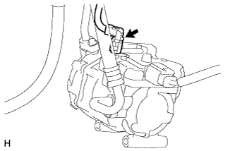 |
Check the connection of the low voltage connector of the compressor with motor assembly.
|
| ||||
| OK | |
|
| 4.CHECK HARNESS AND CONNECTOR (COMPRESSOR WITH MOTOR ASSEMBLY POWER SOURCE CIRCUIT) |
Disconnect connector D12 from the compressor with motor assembly.
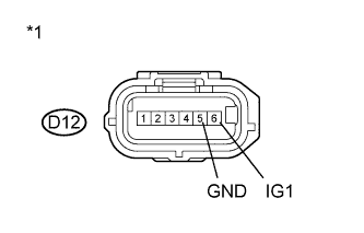 |
Measure the resistance according to the value(s) in the table below.
| Tester Connection | Switch Condition | Specified Condition |
| D12-5 (GND) - Body ground | Power switch off | Below 1 Ω |
| *1 | Front view of wire harness connector (to Compressor with Motor Assembly) |
Turn the power switch on (IG).
Measure the voltage according to the value(s) in the table below.
| Tester Connection | Switch Condition | Specified Condition |
| D12-6 (IG1) - D12-5 (GND) | Power switch on (IG) | 11 to 14 V |
Turn the power switch off.
Connect the compressor with motor assembly connector.
|
| ||||
| OK | |
|
| 5.CHECK HARNESS AND CONNECTOR (POWER MANAGEMENT CONTROL ECU - COMPRESSOR WITH MOTOR) |
Disconnect connector A21 from the power management control ECU.
Disconnect connector D12 from the compressor with motor assembly.
Turn the power switch on (IG).
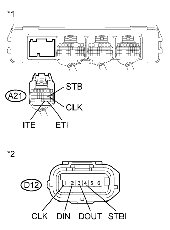 |
Measure the voltage according to the value(s) in the table below.
| Tester Connection | Switch Condition | Specified Condition |
| A21-19 (CLK) - Body ground | Power switch on (IG) | Below 1 V |
| A21-20 (STB) - Body ground | Power switch on (IG) | Below 1 V |
| A21-31 (ITE) - Body ground | Power switch on (IG) | Below 1 V |
| A21-30 (ETI) - Body ground | Power switch on (IG) | Below 1 V |
| *1 | Rear view of wire harness connector (to Power Management Control ECU) |
| *2 | Front view of wire harness connector (to Compressor with Motor Assembly) |
Turn the power switch off.
Measure the resistance according to the value(s) in the table below.
| Tester Connection | Switch Condition | Specified Condition |
| A21-19 (CLK) - D12-1 (CLK) | Power switch off | Below 1 Ω |
| A21-20 (STB) - D12-4 (STBI) | Power switch off | Below 1 Ω |
| A21-31 (ITE) - D12-2 (DIN) | Power switch off | Below 1 Ω |
| A21-30 (ETI) - D12-3 (DOUT) | Power switch off | Below 1 Ω |
| Tester Connection | Switch Condition | Specified Condition |
| A21-19 (CLK) or D12-1 (CLK) - Body ground and other terminals | Power switch off | 10 kΩ or higher |
| A21-20 (STB) or D12-4 (STBI) - Body ground and other terminals | Power switch off | 10 kΩ or higher |
| A21-31 (ITE) or D12-2 (DIN) - Body ground and other terminals | Power switch off | 10 kΩ or higher |
| A21-30 (ETI) or D12-3 (DOUT) - Body ground and other terminals | Power switch off | 10 kΩ or higher |
Connect the compressor with motor assembly connector.
Connect the power management control ECU connector.
|
| ||||
| OK | |
|
| 6.CHECK POWER MANAGEMENT CONTROL ECU |
Disconnect connector D12 from the compressor with motor assembly.
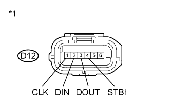 |
Measure the resistance according to the value(s) in the table below.
| Tester Connection | Switch Condition | Specified Condition |
| D12-3 (DOUT) - Body ground | Power switch off | 10 kΩ or higher |
| D12-4 (STBI) - Body ground | Power switch off | 10 kΩ or higher |
| *1 | Front view of wire harness connector (to Compressor with Motor Assembly) |
Turn the power switch on (IG).
Measure the voltage according to the value(s) in the table below.
| Tester Connection | Switch Condition | Specified Condition |
| D12-1 (CLK) - Body ground | Power switch on (IG) | 11 to 14 V |
| D12-2 (DIN) - Body ground | Power switch on (IG) | 11 to 14 V |
| D12-3 (DOUT) - Body ground | Power switch on (IG) | Below 1 V |
| D12-4 (STBI) - Body ground | Power switch on (IG) | Below 1 V |
Turn the power switch off.
Connect the compressor with motor assembly connector.
|
| ||||
| OK | |
|
| 7.CHECK COMPRESSOR WITH MOTOR ASSEMBLY |
Disconnect connector A21 from the power management control ECU.
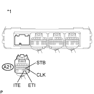 |
Measure the resistance according to the value(s) in the table below.
| Tester Connection | Switch Condition | Specified Condition |
| A21-19 (CLK) - Body ground | Power switch off | 10 kΩ or higher |
| A21-31 (ITE) - Body ground | Power switch off | 10 kΩ or higher |
| *1 | Rear view of wire harness connector (to Power Management Control ECU) |
Turn the power switch on (IG).
Measure the voltage according to the value(s) in the table below.
| Tester Connection | Switch Condition | Specified Condition |
| A21-30 (ETI) - Body ground | Power switch on (IG) | 11 to 14 V |
| A21-20 (STB) - Body ground | Power switch on (IG) | 11 to 14 V |
| A21-19 (CLK) - Body ground | Power switch on (IG) | Below 1 V |
| A21-31 (ITE) - Body ground | Power switch on (IG) | Below 1 V |
Turn the power switch off.
Connect the power management control ECU connector.
|
| ||||
| OK | ||
 | ||
| ||
