LIGHTING SYSTEM > DETAILS


FUNCTION OF MAIN COMPONENTS
  1. LED Headlight System

    Component
    Function
    Main Body ECU (Multiplex Network Body ECU)
    The main body ECU (multiplex network body ECU) receives the HEAD position signal from the light control switch and transmits a signal to the headlight relay.
    Headlight Dimmer Switch Assembly
    Light Control Switch
    The light control switch transmits a HEAD position signal to the main body ECU (multiplex network body ECU).
    Headlight Relay
    The headlight relay supplies power to the LED driver modules (Light Control ECU).
    Headlight Assembly
    Light Emitting Diode (LED)
    The Light Emitting Diode (LED) light shines ahead over a broader area and further forward, increasing the area visible to the driver.
    LED Driver Module (Light Control ECU)
    The LED driver module (Light Control ECU) keeps a constant level of direct current applied to the LED, achieving stable LED illumination.
    Combination Meter Assembly
    Taillight Indicator Light
    The taillight indicator lights up to inform the driver when the taillights turn on.
    Master Warning Light
    The master warning light illuminates to inform the driver when the LED driver module detects malfunctions in this system.
    Multi-information Display
    The multi-information display displays a warning message to inform the driver when the LED driver module (light control ECU) detects a malfunction in this system.

  2. Automatic Headlight Beam Level Control System

    Component
    Function
    Headlight Leveling ECU Assembly
    1. The headlight leveling ECU assembly detects changes of vehicle movement based on the rear height control sensor RH and vehicle speed signal.
    2. The headlight leveling ECU assembly outputs control signals to the headlight leveling motors based on the detected value.
    3. This ECU provides initial set control and a fail-safe function.
    Headlight Assembly
    Headlight Leveling Motor
    1. Based on the signals received from headlight leveling ECU assembly, each headlight leveling motor moves the projector unit in the headlight to vary its angle.
    2. Each headlight leveling motor uses a stepper motor to precisely regulate the angle of the projector unit.
    Main Body ECU (Multiplex Network Body ECU)
    The main body ECU (multiplex network body ECU) receives a HEAD position signal from the light control switch and transmits it to the headlight leveling ECU assembly.
    Headlight Dimmer Switch Assembly
    Light Control Switch
    The light control switch transmits a HEAD position signal to the main body ECU (multiplex network body ECU).
    Rear Height Control Sensor Sub-assembly RH
    The rear height control sensor sub-assembly RH detects vehicle movement and transmits a signal to the headlight leveling ECU assembly.
    Combination Meter Assembly
    The combination meter assembly transmits a vehicle speed signal to the headlight leveling ECU assembly.
    Combination Meter Assembly
    Master Warning Light
    The master warning light illuminates to inform the driver when the headlight leveling ECU assembly detects malfunctions in this system.
    Multi-information Display
    The multi-information display displays a warning message to inform the driver when the headlight leveling ECU assembly detects a malfunction in this system.

  3. Manual Headlight Beam Level Control System

    Component
    Function
    Headlight Leveling Switch
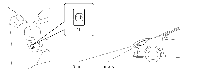
    The level of the headlight can be adjusted between 0 and 4.5, and a switch level status signal is sent to the headlight leveling motor.
    Headlight Leveling Motor
    Headlight leveling motors in accordance with signals from the headlight leveling switch and moves the reflector up and down.

  4. Light Reminder System

    Component
    Function
    Main Body ECU (Multiplex Network Body ECU)
    Outputs taillight illumination signals and driver's door open signals to the combination meter assembly.
    Front Door Courtesy Light Switch Assembly (for Driver)
    Detects whether driver's door is open or closed and transmits a signal to the main body ECU (multiplex network body ECU).
    Combination Meter Assembly
    Receives taillight illumination signals and driver's door open signals from the main body ECU (multiplex network body ECU) when the power switch is turned off and sounds the buzzer.


SYSTEM CONTROL


  1. LED Headlight System

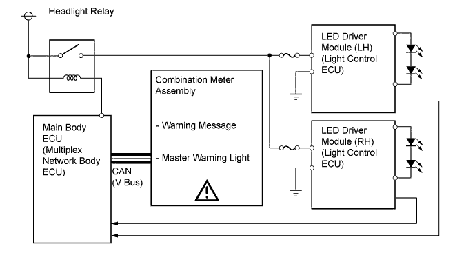
    1. When the light control switch is turned on, the LED driver module (light control ECU) immediately turn on the LEDs (approximately 0.1 sec). In addition, by regulating the output currents flowing into the LEDs at the specified level, the LED driver module (light control ECU) prevent the glare of light due to voltage variation.


    2. If malfunctions occur in the LED headlight system, an LED driver module (light control ECU) transmits fail signals to the main body ECU (multiplex network body ECU). When the main body ECU (multiplex network body ECU) receives fail signals, it transmits signals to the combination meter, warning the driver.

      Y117510E01


  2. Automatic Headlight Beam Level Control System


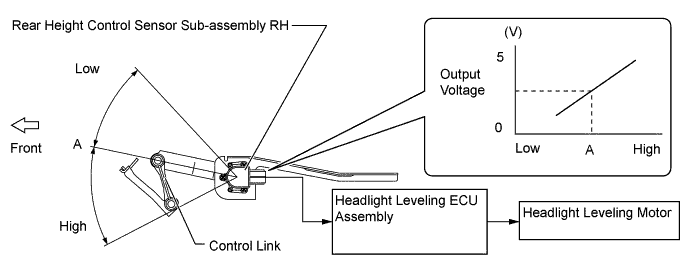
    1. The rear height control sensor sub-assembly RH detects a change in height of the rear shaft in response to the weight applied to the rear of the vehicle when the vehicle is stopped and sends the change amount signal to the headlight leveling ECU. The headlight leveling ECU calculates the vehicle posture based on the change amount and controls the headlight beam level by operating the headlight leveling motor.
      Y117511E01


FUNCTION
  1. Automatic Headlight Beam Level Control System (Models with LED Headlight System)

    1. The automatic headlight beam level control system mainly consists of the headlight leveling ECU assembly, rear height control sensor sub-assembly RH and 2 headlight leveling motors. The headlight leveling ECU assembly controls the system.

    2. The ECU detects the movement of the suspension from the rear height control sensor sub-assembly RH and the vehicle speed from the combination meter sub-assembly.

    3. The ECU then controls the headlight leveling motor based on this information, in order to change the headlight reflector angle.

    4. When the headlight leveling ECU assembly detects that the vehicle is stopped and the power switch is on (IG), the ECU executes the initial setting of the stepper motors.


  2. Manual Headlight Beam Level Control System

    1. The manual headlight beam level control system keeps the beam of the headlight adjusted. to the appropriate level in accordance with the number (weight) of passengers and volume of luggage.


    2. The headlight beam level can be adjusted from 0 to 4.5 by operating the headlight leveling switch.


      Y118365E01


      Text in Illustration 
      *1
      Headlight Leveling Switch
      -
      -

  3. Light Reminder System

    1. The light reminder system warns the driver using a buzzer when the meter ECU inside the combination meter assembly receives the driver's door courtesy light switch signal via the main body ECU (multiplex network body ECU) and the power switch is turned off and the door is opened with the taillights kept on. The buzzer is located inside the combination meter assembly.

      Light Control Switch Position
      Power Switch
      Door
      Buzzer
      TAIL, HEAD
      Switch off
      Open
      Sounds
      Closed
      -


CONSTRUCTION


  1. LED Headlight System


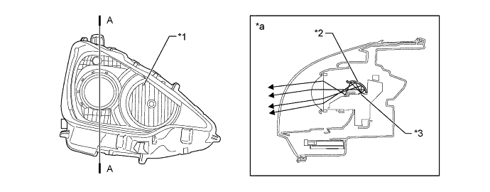
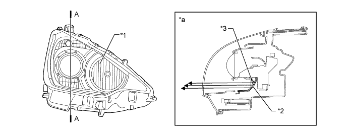
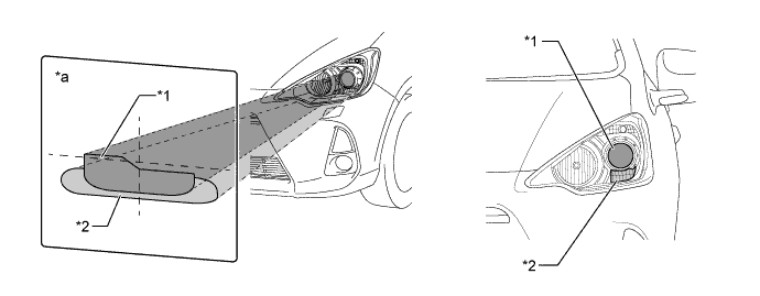
    1. The LED headlight system is newly employed to the low beam headlights. These headlights consist of the upper projector type LED and the lower parabolic cylinder type LED. The upper projector type LED illuminates the distance and the radial parabolic cylinder type LED illuminates the nearby widely.


      V102231E01


      Text in Illustration 
      *1
      LED Headlight for Concentrated Beam Pattern
      *2
      LED Headlight for Widely Diffused Beam Pattern
      *a
      Headlight Beam Pattern Displayed on a Screen
      -
      -


    2. The light from the projector type LED lights are reflected by the reflector and passes through the projector, illuminating an area in the distance. At this time, the illuminated area is optimized by the shape of the reflectors and projector.


      Y117513E01


      Text in Illustration 
      *1
      Headlight Assembly
      *2
      Reflector
      *3
      LED
      -
      -
      *a
      A-A Cross Section
      -
      -


    3. The light from the parabolic cylinder type LED lights are reflected by the optimal reflector shapes provided in the headlights, thus widely illuminating the area around the headlights.


      Y117514E01


      Text in Illustration 
      *1
      Headlight Assembly
      *2
      Reflector
      *3
      LED
      -
      -
      *a
      A-A Cross Section
      -
      -


  2. LED Driver Module


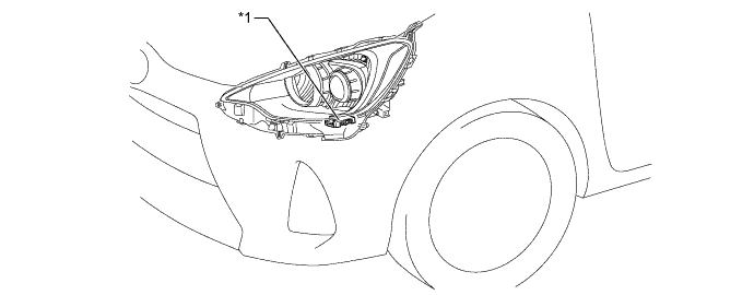
    1. The LED driver modules are placed beneath the headlights and this supplies a constant voltage to the low beams and reduces the changes in the energization current.


      Y117515E01


      Text in Illustration 
      *1
      LED driver Module
      -
      -


FAIL-SAFE
  1. LED Headlight System

    1. The LED driver module (light control ECU) executes the fail-safe actions listed below in accordance with the problem that has been detected.

      Problem
      Outline
      Abnormal Output (Open Circuit or Short Circuit)
      If an abnormal condition (open or short) occurs in the voltage that is output by the LED driver module (light control ECU), the LED driver module (light control ECU) stops illuminating the headlights and will maintain this state until the power is reinstated. Power is reinstated by turning the headlight dimmer switch assembly (light control switch) from off to on.
      Abnormal input voltage (High input voltage)
      When the headlights are on, if the LED driver module (light control ECU) receives a voltage of more than 17 V, it will turn the headlights off. When the input voltage resumes to the normal operating voltage range, the LED driver module will turn the headlights on.
      Abnormal input voltage (Low input voltage)
      When the headlights are on, if the LED driver module (light control ECU) detects that the input voltage has decreased to 6 to 10V, it will dim the headlights. When the input voltage resumes to a normal operating voltage range, the LED driver module will return the headlight brightness to the normal brightness.
      If the LED driver module receives a voltage of less than 6 V, it will turn the headlights off. When the power voltage resumes to more than 8.5 V, the LED driver module will turn the headlights on.

  2. Automatic Headlight Beam Level Control System

    1. If an abnormal condition such as those listed below has been detected, the headlight leveling ECU operates in the fail-safe mode.

      Problem
      Outline
      Power Supply Voltage Malfunction
      Holds the beam at the position of the headlight leveling motor when the abnormality has been detected.
      Rear Height Control Sensor Sub-assembly Data Error During Initialization
      Vehicle Model Code Inconsistent
      Rear Height Control Sensor Sub-assembly Power Supply Malfunction
      Rear Height Control Sensor Sub-assembly Signal Malfunction


DIAGNOSIS
  1. LED Headlight System

    1. If the main body ECU (multiplex network body ECU) detects a malfunction in the LED headlight system, the combination meter assembly flashes the master warning light and indicates the warning message on the multi-information display. At the same time, the Diagnostic Trouble Code (DTC) is stored in memory. The DTC can be read using the intelligent tester. For details, refer to the Repair Manual.

  2. Automatic Headlight Beam Level Control System

    1. When the headlight leveling ECU assembly detects malfunctions in the automatic headlight beam level control system, DTCs are stored in memory.

    2. The DTCs can be read using the intelligent tester. For details, refer to the Repair Manual.