HYBRID TRANSAXLE SYSTEM > GENERAL


OUTLINE
  1. The P510 hybrid vehicle transaxle assembly is used.

  2. Containing a Motor Generator No. 2 (MG2) for driving the vehicle and a Motor Generator No. 1 (MG1) for generating electrical power, this transaxle uses a continuously variable transmission mechanism with a compound gear unit that achieves smooth and quiet operation.

  3. A shift lock system is used.

  4. A shift lock release button has been provided on the shift lever housing, which can be used in an emergency to manually release the shift lock.


  5. To prevent accidental operation, a cover has been provided over the shift lock release button.
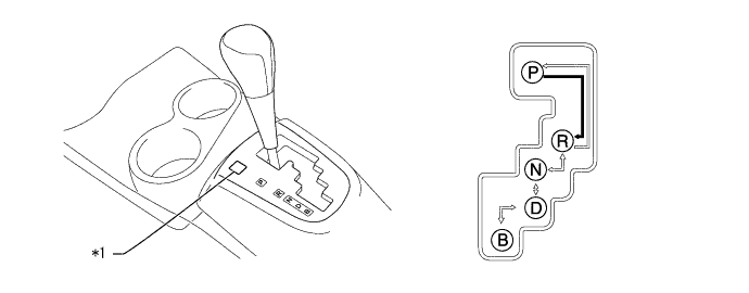

    X123770E01


    Text in Illustration 
    *1
    Shift Lock Release Button Cover
    -
    -
    V100135
    The shift lever can be moved only with the ignition switch ON (IG) or ON (READY) and the brake pedal depressed.
    V100136
    The shift lever can be moved at anytime.


SPECIFICATION

Item
Specification
Transaxle Type
P510
Shift Position
P / R / N / D / B
Compound Gear Unit
Power Split Planetary Gear Unit
No. of Sun Gear Teeth
30
No. of Pinion Gear Teeth
23
No. of Ring Gear Teeth
78
Motor Speed Reduction Planetary Gear Unit
No. of Sun Gear Teeth
22
No. of Pinion Gear Teeth
18
No. of Ring Gear Teeth
58
Counter Gear
No. of Drive Gear Teeth
48
No. of Driven Gear Teeth
49
Final Gear
No. of Drive Gear Teeth
24
No. of Driven Gear Teeth
75
Total Speed Reduction Ratio*1
3.190
Fluid Type
Toyota Genuine ATF WS
Fluid Capacity
Liters (US qts, Imp. qts)
3.3 (3.5, 2.9)
Weight (Reference)*2
kg (lb)
80 (176.4)

HINT:
*1: The ratio of the combination of the counter and final gears.
*2: The figure shown is the weight of the part with fluid and transmission input damper assembly.