Impact Absorbing Structure for Frontal Collision
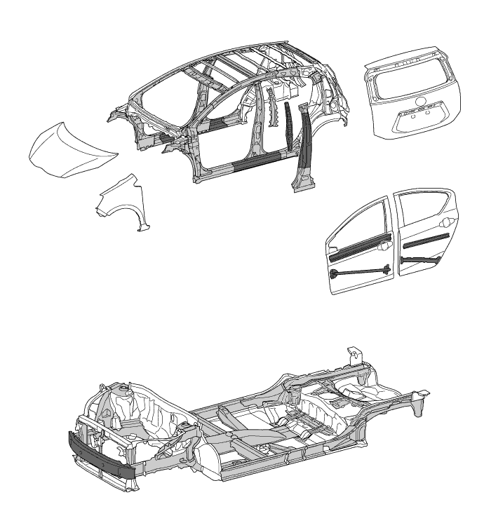
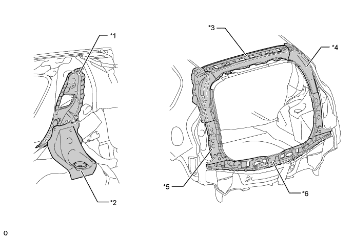
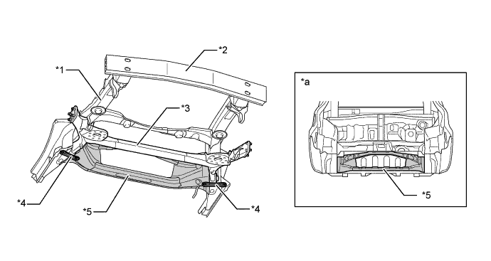
A body structure ensures efficient impact energy absorption and dissipation by the frames from the front to under body to soften the impact to the passengers and minimizes cabin deformation by the rigid cabin frames, in the event of a frontal collision.
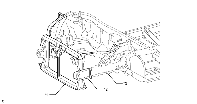
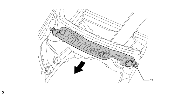
Impact energy during a frontal collision will first be dispersed into the left and right front side members by the front bumper reinforcement. Then it will be dispersed again into the rocker reinforcements and under frames via the front torque boxes.
Impact energy from the upper members will be dispersed into the front door beltline reinforcements and front pillar reinforcement sub-assembly via the Minimum Intrusion Cabin System (MICS) bulks and then distributed to the roof side rail sub-assembly.
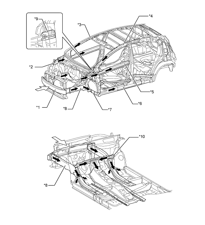
Text in Illustration *1 Front Bumper Reinforcement *2 Upper Member *3 Front Pillar Reinforcement Sub-assembly *4 Roof Side Rail Sub-assembly *5 Front Door Beltline Reinforcement *6 Rocker Reinforce Sub-assembly *7 Front Torque Box *8 Front Side Member *9 Minimum Intrusion Cabin System *10 Front Panel Member Sub-assembly 
Path of Collision Energy 
Frontal Collision Dash panel insulator pads are provided in the lower section of the dash panel to lessen the impact to the legs of the front passengers.
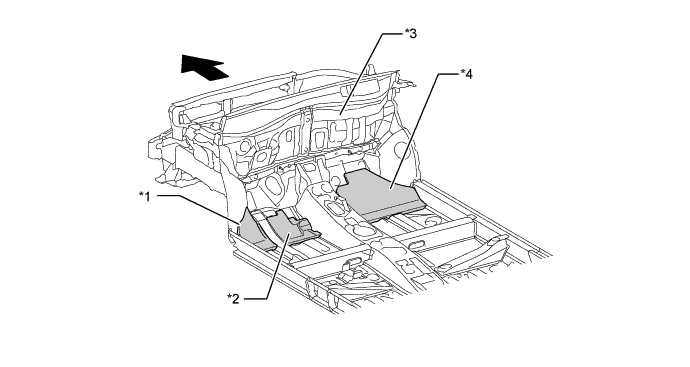
Text in Illustration *1 Foot Rest Area (No. 3 Dash Panel Insulator Pad) *2 Accelerator Pedal Area (No. 2 Dash Panel Insulator Pad) *3 Dash Panel *4 Passenger Seat (No. 4 Dash Panel Insulator Pad) Front - - When the engine is moved toward the cabin due to collision, the brake booster (with master cylinder) will be pushed inward, causing the brake pedal support sub-assembly to detach from the bolt fastening the instrument panel reinforcement, and it will allow the brake pedal support sub-assembly to slide backward along with the bottom of the guide plate. As a result, the brake pedal will move down and forward.
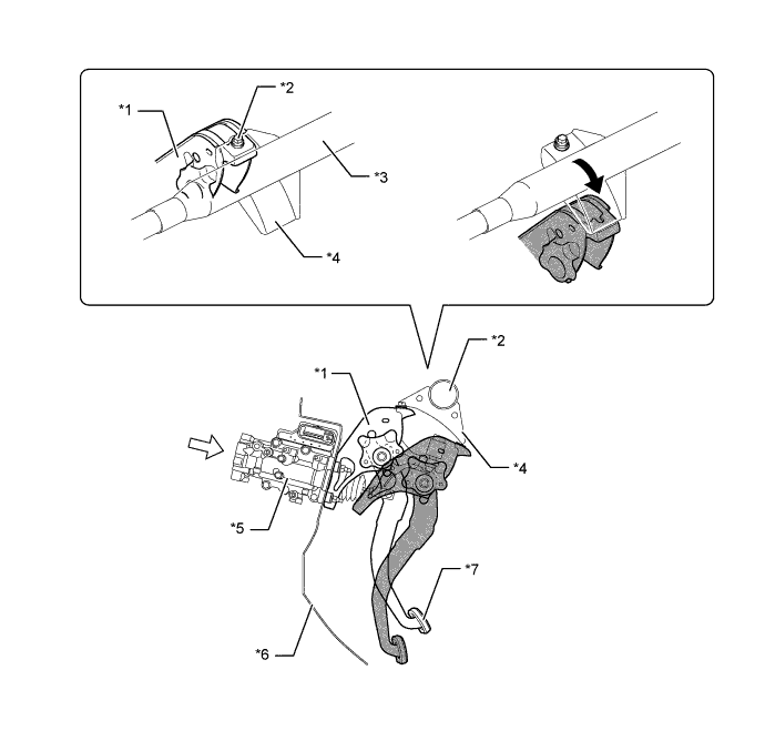
Text in Illustration *1 Brake Pedal Support Sub-assembly *2 Bolt *3 Instrument Panel Reinforcement *4 Guide Plate *5 Brake Booster (with Master Cylinder) *6 Dash Panel *7 Brake Pedal Sub-assembly - Slide Backward Frontal Collision 
During a collision - -
Impact Absorbing Structure for Side Collision
Framework components such as reinforcements have been strengthened and optimally allocated around the door openings to optimize dispersal of impact energy in the event of a side collision.
Ultra high-strength sheet steel is used for the rocker outer reinforcements, center pillar reinforcements, center pillar hinge reinforcements, and high-strength sheet steel is used for the center pillar inner reinforcements, rail outer reinforcements and roof reinforcements to ensure bearing force.
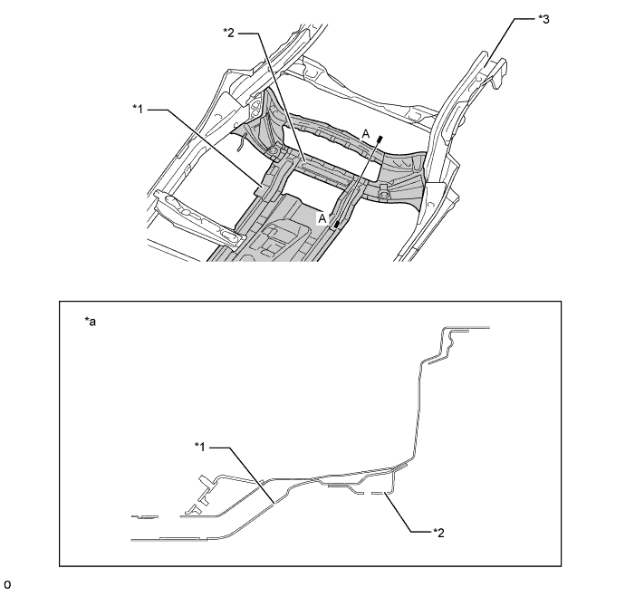
Bulkheads are placed inside the rocker reinforcements to efficiently transmit impact energy to the front floor cross members as well as preventing the rocker reinforcement deformation.
Optimal placement of the front and rear door side impact protection beams enables a construction that efficiently transmits load.
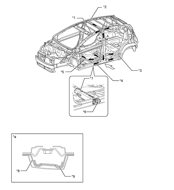
Text in Illustration *1 Roof Side Rail Sub-assembly *2 Roof Panel Reinforcement *3 Rear Door Side Impact Protection Beam *4 Rocker Reinforce Sub-assembly *5 Front Door Side Impact Protection Beam *6 Bulkhead *7 Floor Cross Member *8 Center Body Pillar Outer Reinforcement *9 Center Body Pillar Upper Hinge Reinforcement - - *a A-A Cross Section - - Path of Collision Energy Side Collision An impact absorbing pad (front door trim pad) is installed on the inside of the front door to soften the impact to the hip area of the front passenger. In addition, an impact absorbing pad (door trim lower pad) to soften the impact to the hip area of the rear passenger are installed on the inside of the rear door.
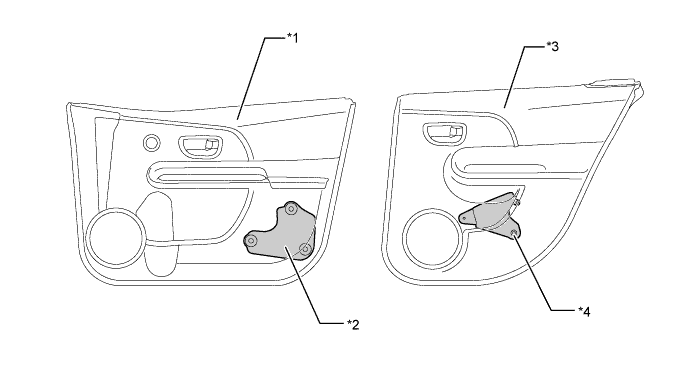
Text in Illustration *1 Front Door Trim Board Sub-assembly *2 Impact Absorbing Pad *3 Rear Door Trim Board Sub-assembly *4 Impact Absorbing Pad Impact absorbing structure is used in consideration of an occupant's head impacting a pillar or the roof side in reaction to a collision.
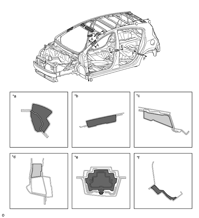
Impact energy to the occupant's head will be reduced by the deformation of the ribbed section designed for impact absorption and hard urethane, provided inside the pillar garnish and roof headlining.
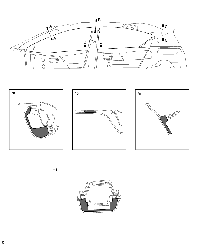
Text in Illustration *a A-A Cross Section *b B-B Cross Section *c C-C Cross Section *d D-D Cross Section Impact Absorbing Material - -
Impact Absorbing Structure for Roof Collision
The frames have been strengthened to minimize the deformation of the cabin when a load is applied to the vehicle in the event of the vehicle roll over.
An inner reinforcement is provided at the corner of the inner front pillar to minimize the deformation of the front pillar.
A roof upper reinforcement has been provided in addition to a roof reinforcement to ensure rigidity and minimize deformation of the cabin.
The thicknesses of the front head and header extensions have been optimized to minimize deformation of the windshield frame.
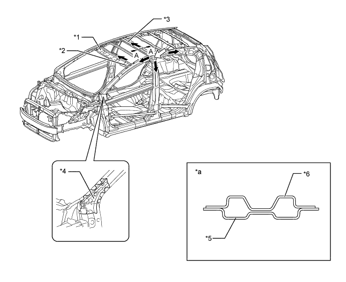
Text in Illustration *1 Windshield Header Panel Inner *2 No. 2 Front Body Pillar Reinforcement Upper Out *3 Center Roof Panel Reinforcement *4 Front Body Pillar Lower Inner *5 Roof Panel Center Reinforcement *6 Roof Panel Center Reinforcement Upper *a A-A Cross Section - - Path of Collision Energy Impact
Lessening Pedestrian Injury
An energy absorber is provided at the front of the front bumper reinforcement to dampen the impact to the legs in the event of a collision with a pedestrian.
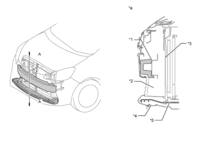
Text in Illustration *1 Front Bumper Energy Absorber *2 Lower Grille *3 Front Bumper Reinforcement *4 Front Bumper Cover *5 Front Lower Bumper Absorber - - *a A-A Cross Section - - A vertical ribbed structure is used on the hood inner panel in order to allow the hood to collapse easily, so that a collision impact can be reduced by using the whole part of the hood.
Ridges are provided in appropriate positions of the hood inner panel and hood reinforcement respectively, in order to lessen the impact energy to a pedestrian during a collision by allowing both structures to collapse and to absorb the impact energy.
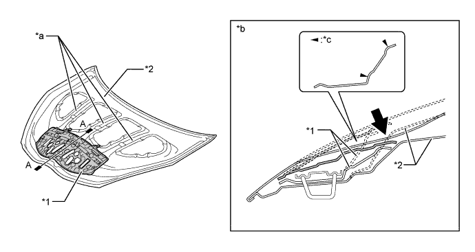
Text in Illustration *1 Hood Reinforcement *2 Hood Inner Panel *a Vertical Ribbed Structure *b A-A Cross Section *c Ridges - - Impact - - In the front fender installation areas, a crushable impact absorbing bracket (front apron to cowl side member plate) has been provided so as to lessen the impact to a pedestrian in the event of a collision.
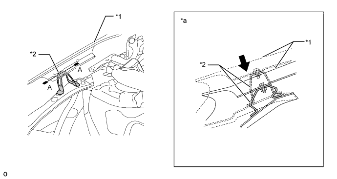
Text in Illustration *1 Front Fender Panel (Front Fender Sub-assembly) *2 Impact Absorbing Bracket (Front Apron to Cowl Side Member Plate) *a A-A Cross Section - - Impact - - In order to reduce the impact applied from above, the cowl employs a crushable structure with collapsible ridges that are considerably arranged.
The easily collapsible cowl louver has been provided so that it can collapse if an impact force will occur from above, reducing the impact energy.
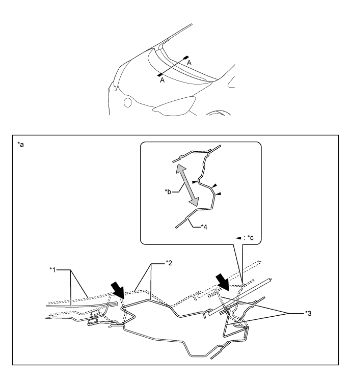
Text in Illustration *1 Hood Panel *2 No.1 Cowl Top Ventilator Louver Center *3 Cowl Louver *4 Cowl Top Panel Inner *a A-A Cross Section *b Open Section Structure *c Ridges - - Impact - -
Aerodynamics
In order to reduce the air that flows to the area behind the vehicle, all the surfaces of the upper body have been made flush, also the vehicle height has been lowered to reduce the frontal projected area, the roof rear end angle has been optimally adjusted, and an aero corner (squared corner edge) has been provided on the rear bumper side ends. Furthermore, the side body surfaces have been trimmed to reduce drag, delivering excellent aerodynamics.
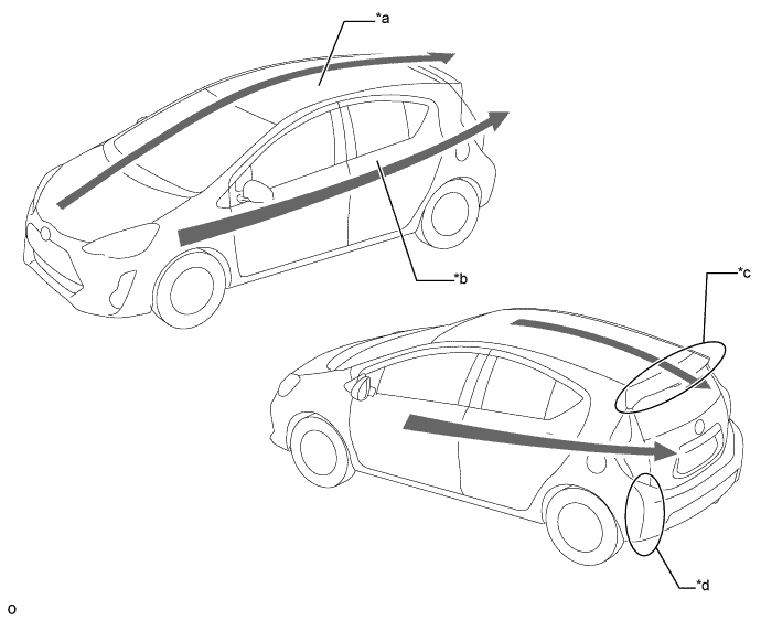
Text in Illustration *a Frontal Projected Area Reduction *b Reduction of Air Resistance by Narrowing the Flat Surface Area *c Optimum Length and Angle of Rear Spoiler *d Sharp Corner Edge at the Side or Rear Bumper Cover The pagoda roof, a curved surface roof top, is used to reduce the frontal projected area so as to reduce wind drag while driving, improving the fuel efficiency.
Along with the flush upper body surfaces, fins that route air flowing over the body surfaces have been provided on the outer rear view mirror assembly and rear combination light assembly to minimize air turbulence, reducing wind drag. As a result, improvement in the efficient fuel consumption has been achieved.
Through use of airflow routing components that control air flowing over the under body surface, the design delivers excellent aerodynamics, offering comfortable stability when the vehicle is driven straight at high speeds and good maneuvering stability.
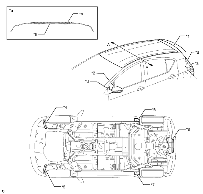
Text in Illustration *1 Rear Spoiler *2 Outer Rear View Mirror Assembly *3 Rear Combination Light Assembly *4 Front Spat LH (Front Wheel Opening Extension Pad LH) *5 Front Spat RH (Front Wheel Opening Extension Pad RH) *6 Rear Spat LH (Rear Wheel Opening Extension Pad LH) *7 Rear Spat RH (Rear Wheel Opening Extension Pad RH) *8 No. 1 Floor Under Cover *a A-A Cross Section *b Pagoda Roof *c General Roof *d Fin A rear spoiler has been provided at the roof end for all models to prevent air, which flows from the roof, from entering the area behind the vehicle, reducing wind drag and resulting in improvement in fuel efficiency. As for the style of the rear spoiler, it is shaped so that the body line can seamlessly extend from the roof panel.
In accordance with the model specifications, a large rear spoiler has been made available as an option. The large rear spoiler has openings and is a wing-shaped structure, thus, air that flows over the wing-shaped spoiler surface will produce down force, ensuring the maneuvering stability further.
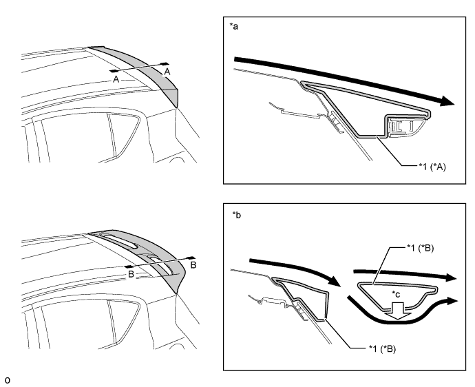
Text in Illustration *A Standard Type *B Large Type *1 Rear Spoiler - - *a A-A Cross Section *b B-B Cross Section *c Down Force - - Airflow - - The front and rear spats block air flowing toward the tires, reducing air that flows into the wheel houses. Reducing the air will minimize interference with airflow generated by tire revolution. By minimizing air turbulence that occurs around the tires, the maneuvering stability has been ensured.
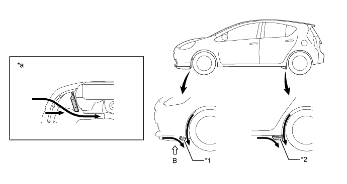
Text in Illustration *1 Front Spat (Front Wheel Opening Extension Pad LH) *2 Rear Spat (Rear Wheel Opening Extension Pad LH) *a View from B - - Airflow - - A floor under cover has been provided on the rear bumper cover to regulate air that flows over the bottom surface of the rear bumper cover, reducing wind drag and resulting in the improvement in efficient fuel consumption. Furthermore, by adding the fin, the maneuvering stability has also been enhanced.
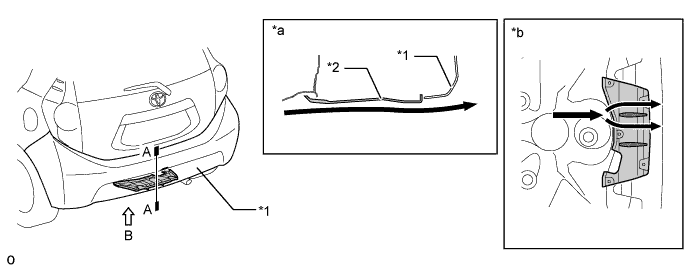
Text in Illustration *1 Rear Bumper Cover *2 No. 1 Floor Under Cover *a A-A Cross Section *b View from B Airflow - - The front fender liner profile has been designed to offer a rectification effect, and it regulates air that flows into the front fender liner to help it flow out toward the side of the body, achieving the excellent maneuvering stability.
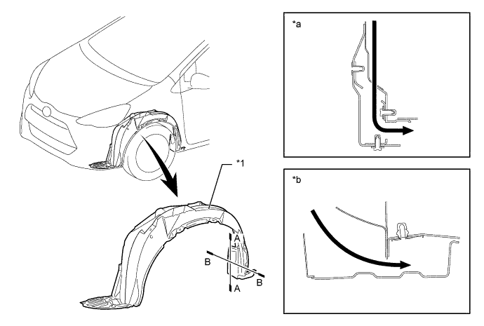
Text in Illustration *1 Front Fender Liner - - *a A-A Cross Section *b B-B Cross Section Airflow - - The structure of the side seals has been made to allow air around the rear tires to stream through the side seals, so as to enhance the grip of the rear tires as well as reduce the vibration of the body. As a result, the excellent maneuvering stability can be provided.
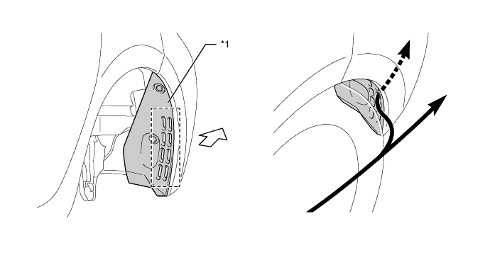
Text in Illustration *1 Rear Bumper Side Seal - - Airflow Rear of the Vehicle