 |
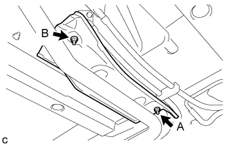
Install the front No. 4 floor heat insulator with the 2 nuts.
- Torque:
- Nut A:
- 5.4 N*m{ 55 kgf*cm , 48 in.*lbf }
- Nut B:
- 5.5 N*m{ 56 kgf*cm , 49 in.*lbf }
REAR BRAKE FLEXIBLE HOSE > INSTALLATION |
| 1. INSTALL REAR FLEXIBLE HOSE |
Install the rear flexible hose with 2 new clips.
Using a union nut wrench, connect the 2 brake lines to the rear flexible hose while holding the rear flexible hose with a wrench.
| 2. CONNECT CABLE TO NEGATIVE AUXILIARY BATTERY TERMINAL |
| 3. INSTALL NO. 1 FUEL TANK PROTECTOR SUB-ASSEMBLY (for RH Side) |
Install the No. 1 fuel tank protector sub-assembly with the bolt.
Install the clip.
| 4. INSTALL FRONT NO. 4 FLOOR HEAT INSULATOR (for RH Side) |
|
Install the front No. 4 floor heat insulator with the 2 nuts.
| 5. BLEED BRAKE LINE |
Separate the center No. 1 cowl top ventilator louver.
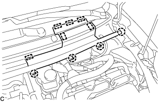 |
for LHD:
Disengage the 4 claws and 6 guides, and separate the center No. 1 cowl top ventilator louver.
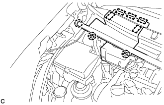 |
for RHD:
Disengage the 3 claws and 5 guides, and separate the center No. 1 cowl top ventilator louver.
Bleed brake line.
Remove the brake master cylinder reservoir filler cap assembly.
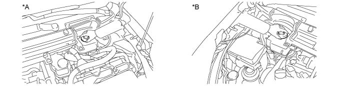
| *A | for LHD | *B | for RHD |
Add brake fluid into the reservoir between the MAX and MIN lines on the brake fluid reservoir.
Connect the intelligent tester to the DLC3 and turn the power switch on (IG).
Turn the intelligent tester on and enter the following menus: Chassis / ABS/VSC/TRC / Air Bleeding.
Select "Usual air bleeding" on the intelligent tester display, and bleed air from the brake fluid following the instructions on the intelligent tester.
After air bleeding, tighten each bleeder plug.
Clear the DTCs (Click here).
Turn the intelligent tester off and turn the power switch off.
Install the brake master cylinder reservoir filler cap.
Inspect for brake fluid leaks.
Install the center No. 1 cowl top ventilator louver.
for LHD:
Engage the 4 claws and 6 guides to install the center No. 1 cowl top ventilator louver.
for RHD:
Engage the 3 claws and 5 guides to install the center No. 1 cowl top ventilator louver.
| 6. INSTALL REAR WHEEL |