Home › Drivetrain › P510 HYBRID TRANSMISSION / TRANSAXLE › TRANSMISSION CONTROL CABLE

TRANSMISSION CONTROL CABLE > INSTALLATION

for Preparation Click here


1. INSTALL NO. 2 TRANSMISSION CONTROL CABLE CLAMP

HINT:
Perform this procedure only when replacement of the No. 2 transmission control clamp is necessary.


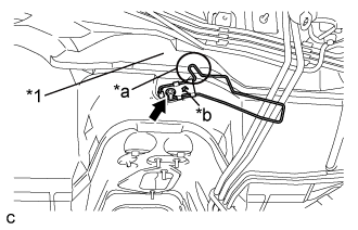
    C251103E01
  1. Install the No. 2 transmission control clamp to the body with the nut.
    Text in Illustration 
    *1
    Dash Silencer
    *a
    Pushing Against The Dash Silencer
    *b
    Arrow

    Torque:
    5.0 N*m{ 51 kgf*cm , 44 in.*lbf }

    NOTICE:
    1. Install the No. 2 transmission control clamp so that its arrow mark points to the front of the vehicle.
    2. Make sure that the transmission control cable support stopper is pushing against the dash silencer.
2. INSTALL TRANSMISSION CONTROL CABLE ASSEMBLY
  1. Pass the transmission control cable into the vehicle and install the transmission control cable assembly to the body using the 3 nuts.

    Torque:
    5.0 N*m{ 51 kgf*cm , 44 in.*lbf }

  1. Install the transmission control cable assembly to the transmission control cable clamp and transmission control cable support.

  1. Install the transmission control cable assembly to the No. 1 transmission control cable bracket with a new clip.


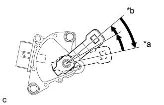
    C250073E02
  1. Rotate the control shaft lever clockwise until it stops, and then from that position rotate it counterclockwise by 2 notches to set it to the N position.
    Text in Illustration 
    *a
    P Position
    *b
    N Position

  1. Install the transmission control cable assembly onto the transmission control shaft lever with the nut.

    Torque:
    12 N*m{ 122 kgf*cm , 9 ft.*lbf }


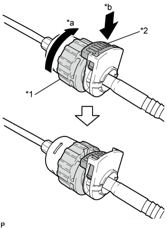
    C195134E04
  1. Rotate the nut of the transmission control cable assembly approximately 180° in the direction shown in the illustration, and while holding the nut, push in the lock.
    Text in Illustration 
    *1
    Nut
    *2
    Lock
    *a
    Rotate Approximately 180°
    *b
    Push In


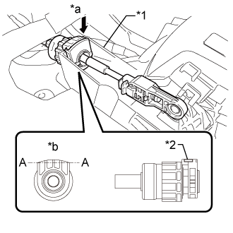
    C250999E01
  1. Install the transmission control cable assembly to the shift lever plate.
    Text in Illustration 
    *1
    Shift Lever Plate
    *2
    Lock
    *a
    Install
    *b
    Projecting Part

    NOTICE:
    1. Install the cable outer with the projecting part facing upwards.
    2. After installation, make sure that the cable outer lock is projecting from A as shown in the illustration.
    3. Make sure that the transmission control cable assembly are securely locked.


    C249909
  1. Confirm that the shift lever is in N, and then install the cable end to the shift lever assembly.

    NOTICE:
    1. Securely install the cable end to the shift lever assembly.
    2. Install the cable end so that its adjustment lock section is on the driver side.


3. ADJUST SHIFT LEVER POSITION
  1. Apply the parking brake and move the shift lever to N.

  1. Remove the rear console box assembly (Click here).


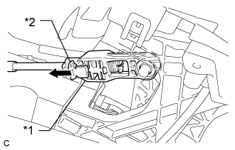
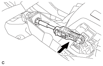
    C258106E01
  1. Slide the adjuster case cover in the direction shown by the arrow.
    Text in Illustration 
    *1
    Adjuster Case
    *2
    Adjuster Case Cover


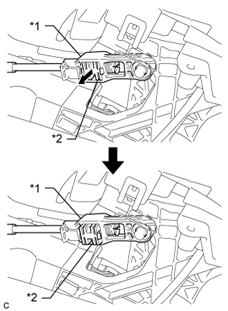
    C258107E01
  1. Using a precision screwdriver, pull out the lock piece of the adjuster case.
    Text in Illustration 
    *1
    Adjuster Case
    *2
    Lock Piece

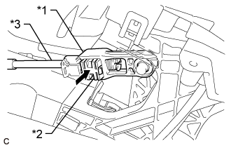
  1. Using your fingers, gently pull the cable rod towards the rear of the vehicle to remove backlash.


    C258108E01
  1. Push in the lock piece of the adjuster case to lock it.
    Text in Illustration 
    *1
    Adjuster Case
    *2
    Lock Piece
    *3
    Cable Rod


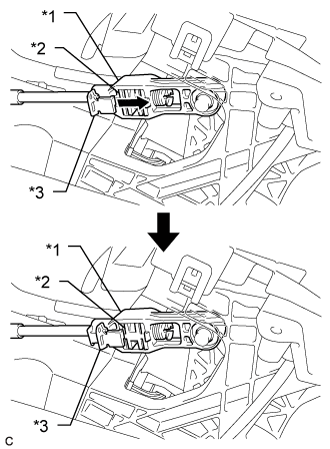
    C258109E01
  1. Move the adjuster case cover in the direction shown by the arrow.
    Text in Illustration 
    *1
    Adjuster Case
    *2
    Lock Piece
    *3
    Adjuster Case Cover

    NOTICE:
    If the adjuster case cover is not moved far enough so that the adjuster case cover engages the lock piece, the cable will not be able to lock, and reliable shift operation will not be possible.

  1. Install the rear console box assembly (Click here).


4. INSTALL FRONT NO. 1 FLOOR HEAT INSULATOR SUB-ASSEMBLY
  1. Install the No. 1 floor heat insulator sub-assembly with the 2 bolts and nut.

    Torque:
    5.5 N*m{ 56 kgf*cm , 49 in.*lbf }


5. INSTALL FRONT EXHAUST PIPE ASSEMBLY


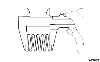
    A077857
  1. Using a vernier caliper, measure the free length of the compression springs.
    Minimum (front)
    41.5 mm (1.64 in.)
    Minimum (rear)
    38.5 mm (1.52 in.)

    HINT:
    If the free length is less than minimum, replace the compression spring.

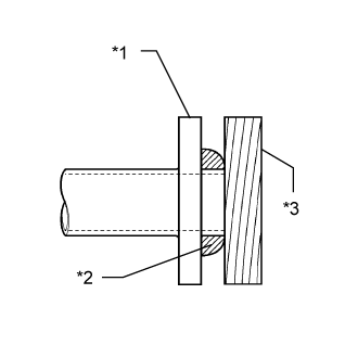
  1. Fully insert 2 new gaskets to the exhaust manifold converter and front exhaust pipe assembly.


    A181728E17
  1. Using a plastic hammer and wooden block, tap in each new gasket until its surface is flush with the exhaust manifold and front exhaust pipe assembly.
    Text in Illustration 
    *1
    Exhaust Manifold and Front Exhaust Pipe Assembly
    *2
    Gasket
    *3
    Wooden Block

    NOTICE:
    1. Be careful with the installation direction of the gaskets.
    2. Do not reuse the gaskets.
    3. Do not damage the gaskets.
    4. Do not push in the gaskets by using the exhaust pipe when connecting it.

  1. Connect the front exhaust pipe assembly to the 3 exhaust pipe supports.


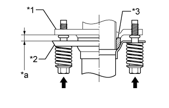
  1. Install the front exhaust pipe assembly with the 2 compression springs, 2 bolts and 2 nuts.

    Torque:
    43 N*m{ 438 kgf*cm , 32 ft.*lbf }


    HINT:
    A258941E01
    After installation, check that the gaps between the flanges of the exhaust manifold and front exhaust pipe assembly are consistent front-to-rear and left-to-right.
    Text in Illustration 
    *1
    Exhaust Manifold
    *2
    Front Exhaust Pipe Assembly
    *3
    Gasket
    *a
    Space between flanges: 8.5 mm (0.335 in.)


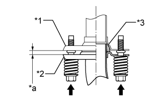
  1. Install the front exhaust pipe assembly with the 2 compression springs and 2 bolts.

    Torque:
    43 N*m{ 438 kgf*cm , 32 ft.*lbf }


    HINT:
    A258966E01
    After installation, check that the gaps between the flanges of the tail exhaust pipe assembly and front exhaust pipe assembly are consistent front-to-rear and left-to-right.
    Text in Illustration 
    *1
    Tail Exhaust Pipe Assembly
    *2
    Front Exhaust Pipe Assembly
    *3
    Gasket
    *a
    Space between flanges: 6.5 mm (0.256 in.)


6. INSTALL REAR CONSOLE BOX ASSEMBLY
(Click here)


7. INSPECT SHIFT LEVER POSITION
  1. While moving the shift lever from N to each position, check that the lever moves smoothly and that the shift position indicator comes on properly according to the shift lever position.

  1. Turn the power switch on (READY) and check the following:

    1. When the shift lever is moved to D, the vehicle moves forward.

    2. When the shift lever is moved to R, the vehicle moves in reverse.

      NOTICE:
      The vehicle should not move when the shift position indicator is off.


8. INSPECT FOR EXHAUST GAS LEAK