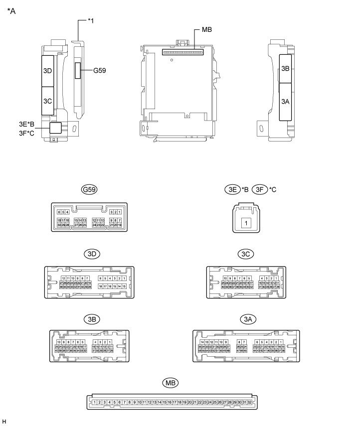
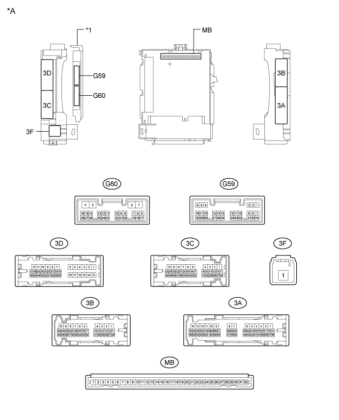
Terminal No. (Symbol)
| Wiring Color
| Terminal Description
| Condition
| Specified Condition
|
3C-2 - Body ground*3
| G - Body ground
| Taillight relay drive signal output
| Light control switch in tail or head position
| 11 to 14 V
|
Light control switch off
| Below 1 V
|
3C-7 - Body ground*3, *4
| L - Body ground
| Front fog light drive output
| Light control switch in tail position, front fog light switch on
| 11 to 14 V
|
Light control switch in tail position, front fog light switch off
| Below 1 V
|
3C-18 (HRLY) - Body ground*3
| V - Body ground
| Headlight relay drive output
| Light control switch in head position
| Below 1 V
|
Light control switch not in head position
| 11 to 14 V
|
3C-35 (DIM) - Body ground*3
| P - Body ground
| High beam headlight drive output
| Dimmer switch in high or high flash position
| Below 1 V
|
Dimmer switch in low position
| 11 to 14 V
|
3D-10 - Body ground*3
| G - Body ground
| Taillight relay drive signal output
| Light control switch in tail or head position
| 11 to 14 V
|
Light control switch off
| Below 1 V
|
G59-5 (HU) - Body ground*3
| L - Body ground
| Dimmer switch high position signal input
| Dimmer switch in high position
| Below 1 V
|
Dimmer switch not in high position
| Pulse generation
|
G59-8 (HF) - Body ground*3
| L - Body ground
| Dimmer switch high flash position signal input
| Dimmer switch in high flash position
| Below 1 V
|
Dimmer switch not in high flash position
| Pulse generation
|
G59-27 (FFOG) - Body ground*3, *4
| GR - Body ground
| Front fog light switch input
| Front fog light switch on
| Below 1 V
|
Front fog light switch off
| Pulse generation
|
G59-29 (HEAD) - Body ground*3
| L - Body ground
| Light control switch head position input
| Light control switch in head position
| Below 1 V
|
Light control switch not in head position, power switch off
| Pulse generation
|
Light control switch not in head position, power switch on (IG)
| 11 to 14 V
|
G59-30 (TAIL) - Body ground
| SB - Body ground
| Light control switch tail position signal input
| Light control switch in tail or head position
| Below 1 V
|
Light control switch in neither tail nor head position, power switch off
| Pulse generation
|
Light control switch in neither tail nor head position, power switch on (IG)
| 11 to 14 V
|