Home › Engine / Hybrid System › HYBRID / BATTERY CONTROL › BATTERY SMART UNIT

BATTERY SMART UNIT > REMOVAL

for Preparation Click here


1. PRECAUTION
(Click here)


2. REMOVE SERVICE PLUG GRIP
(Click here)


3. REMOVE REAR SEAT CUSHION ASSEMBLY


    B297552E01
  1. Disengage the 2 clips.
    Text in Illustration 
    *a
    RH Side
    *b
    LH Side


    B296114E01
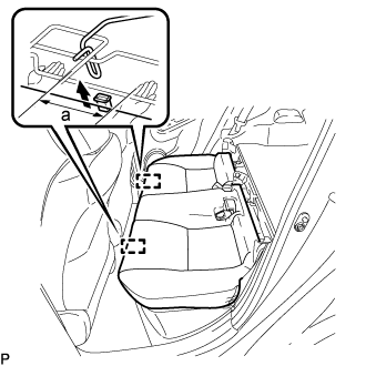
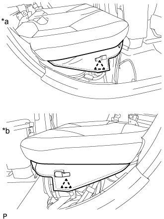
  1. Disengage the hook of the rear seat cushion assembly from the vehicle body as shown in the illustration.
    Standard Measurement 
    a
    100 mm (3.94 in.) or less

    NOTICE:
    Follow the instructions below carefully as the cushion frame can be deformed easily.


    1. Choose a hook to disengage first. Place your hands near the hook as shown in the illustration. Then lift the seat cushion to disengage the hook.

    2. Repeat the step above for the other hook.

  1. Remove the rear seat cushion assembly.

    NOTICE:
    Be careful not to damage the vehicle body.


4. REMOVE REAR SEAT CUSHION LEG SUB-ASSEMBLY


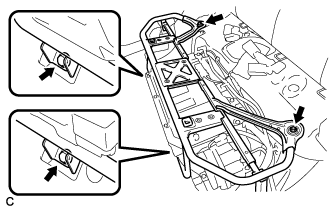
    A266710
  1. Remove the 4 bolts and rear seat cushion leg sub-assembly.


5. REMOVE INVERTER TERMINAL COVER


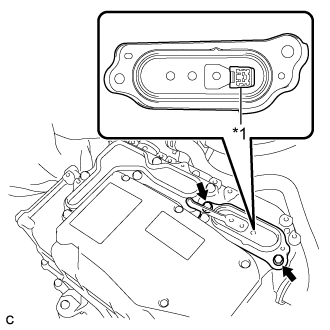
    A266706E01
  1. Remove the 2 bolts and inverter terminal cover.
    Text in Illustration 
    *1
    Interlock Connector

    CAUTION:
    An interlock connector is installed to the inverter terminal cover. Make sure to remove the inverter terminal cover before removing the inverter cover.

    NOTICE:
    Make sure to pull the inverter cover straight up, as a connector is connected to the bottom of the cover.


6. REMOVE INVERTER COVER

CAUTION:
Wear insulated gloves.


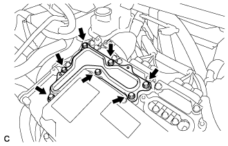
    A266688
  1. Remove the 7 bolts and inverter cover.

    CAUTION:
    An interlock connector is installed to the inverter terminal cover. Make sure to remove the inverter terminal cover before removing the inverter cover.


7. CHECK TERMINAL VOLTAGE

CAUTION:
Wear insulated gloves.

NOTICE:
Do not allow any foreign matter or water to enter the inverter with converter assembly.


    A267098
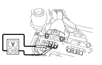
  1. Using a voltmeter, measure the voltage between the terminals of the 2 phase connectors.

    Standard voltage:
    0 V

    HINT:
    Use measuring range of DC 750 V or more on the voltmeter.


8. INSTALL INVERTER COVER

CAUTION:
Wear insulated gloves.


    A266688E01
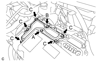
  1. Temporarily install the inverter cover with the 7 bolts to the inverter with converter assembly.

    CAUTION:
    An interlock connector is installed to the inverter terminal cover. Make sure to install the inverter terminal cover after installing the inverter cover.

    NOTICE:
    Visually confirm that the inverter cover waterproofing rubber is securely installed before installing the inverter cover.

  1. Fully tighten the bolt (A).

    Torque:
    11 N*m{ 112 kgf*cm , 8 ft.*lbf }

  1. Fully tighten the bolt (B).

    Torque:
    11 N*m{ 112 kgf*cm , 8 ft.*lbf }

  1. Fully tighten the 5 bolts (C).

    Torque:
    11 N*m{ 112 kgf*cm , 8 ft.*lbf }


9. INSTALL INVERTER TERMINAL COVER

CAUTION:
Wear insulated gloves.


    A266706E01
  1. Temporarily install the inverter terminal cover with the 2 bolts to the inverter with converter assembly.
    Text in Illustration 
    *1
    Interlock Connector

    CAUTION:
    An interlock connector is installed to the inverter terminal cover. Make sure to install the inverter terminal cover after installing the inverter cover.

    NOTICE:
    1. Visually confirm that the inverter terminal cover waterproofing rubber is securely installed before installing the inverter terminal cover.
    2. Make sure that the interlock connector is fully engaged.

  1. Fully tighten the bolt (A).

    Torque:
    11 N*m{ 112 kgf*cm , 8 ft.*lbf }

  1. Fully tighten the bolt (B).

    Torque:
    11 N*m{ 112 kgf*cm , 8 ft.*lbf }


10. REMOVE NO. 1 HYBRID BATTERY EXHAUST DUCT


    A266728
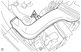
  1. Remove the clip and No. 1 hybrid battery exhaust duct.


11. DISCONNECT WIRE HARNESS


    A266711
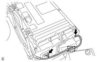
  1. Disconnect the 2 connectors.

  1. Disengage the clamp.


12. REMOVE HYBRID BATTERY SERVICE PLUG COVER


    A266768
  1. Remove the 2 nuts and hybrid battery service plug cover.


13. REMOVE NO. 1 HYBRID BATTERY SHIELD SUB-ASSEMBLY

CAUTION:
Wear insulated gloves.


    A266769
  1. Remove the bolt and electric vehicle battery plug as shown in the illustration.
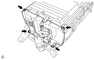


    A266770
  1. Remove the 2 bolts, 2 nuts and No. 1 hybrid battery shield sub-assembly.


14. REMOVE NO. 2 HYBRID VEHICLE BATTERY CARRIER BRACKET SUB-ASSEMBLY

CAUTION:
Wear insulated gloves.


    A266771
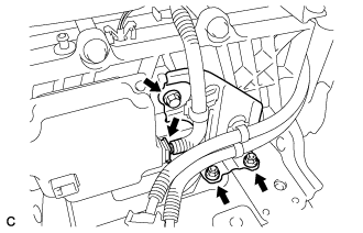
  1. Disconnect the battery smart unit connector.

  1. Remove the bolt and 2 nuts.


    A266772
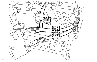
  1. Disengage the 3 clamps and remove the No. 2 hybrid vehicle battery carrier bracket sub-assembly.


15. REMOVE BATTERY SMART UNIT

CAUTION:
Wear insulated gloves.


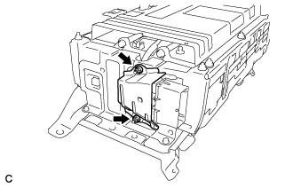
  1. w/o Wiring Harness Protector:


      A266715
    1. Disconnect the battery smart unit connector.

      NOTICE:
      Insulate the removed terminals with insulating tape.

    2. Remove the bolt and battery smart unit from the HV battery.


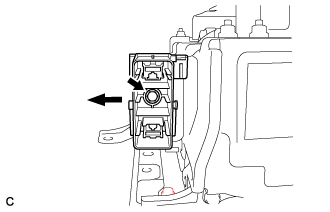
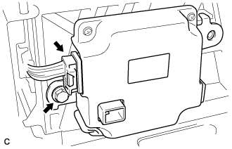
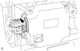
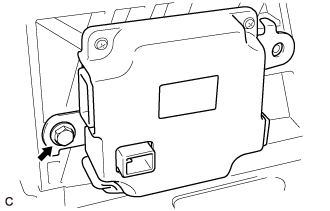
  1. w/ Wiring Harness Protector:


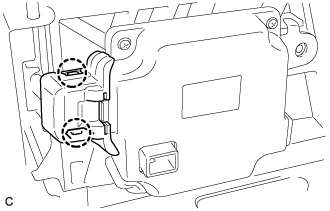
      A311362
    1. Disengage the 2 claws to remove the wiring harness protector cover from the battery smart unit connector.


    2. A309730
    3. Disconnect the battery smart unit connector.
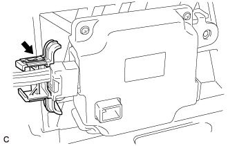
      NOTICE:
      Insulate the removed terminals with insulating tape.


    4. A309731
    5. Remove the wiring harness protector from the battery smart unit connector.


    6. A311369
    7. Remove the bolt and battery smart unit from the HV battery.