POWER WINDOW MASTER SWITCH > INSPECTION |
| 1. INSPECT POWER WINDOW REGULATOR MASTER SWITCH ASSEMBLY (for LHD) |
|
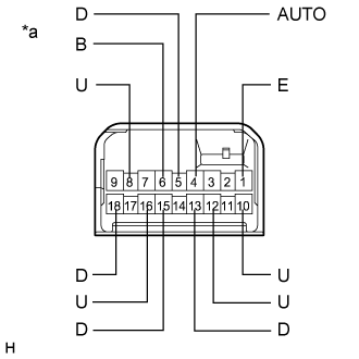
Check the switch function.
Turn the window lock switch off and operate the switches on the power window regulator master switch assembly.
Measure the resistance according to the value(s) in the table below.
| Tester Connection | Switch Condition | Specified Condition |
| 4 (AUTO) - 1 (E) | AUTO UP | Below 1 Ω |
| 8 (U) - 1 (E) | AUTO UP | Below 1 Ω |
| 8 (U) - 1 (E) | MANUAL UP | Below 1 Ω |
| 5 (D) - 1 (E) | MANUAL DOWN | Below 1 Ω |
| 4 (AUTO) - 1 (E) | AUTO DOWN | Below 1 Ω |
| 5 (D) - 1 (E) | AUTO DOWN | Below 1 Ω |
| Tester Connection | Switch Condition | Specified Condition |
| 6 (B) - 16 (U) | UP | Below 1 Ω |
| 1 (E) - 15 (D) | UP | Below 1 Ω |
| 1 (E) - 16 (U) | OFF | Below 1 Ω |
| 1 (E) - 15 (D) | OFF | Below 1 Ω |
| 1 (E) - 16 (U) | DOWN | Below 1 Ω |
| 6 (B) - 15 (D) | DOWN | Below 1 Ω |
| Tester Connection | Switch Condition | Specified Condition |
| 6 (B) - 10 (U) | UP | Below 1 Ω |
| 1 (E) - 18 (D) | UP | Below 1 Ω |
| 1 (E) - 18 (D) | OFF | Below 1 Ω |
| 1 (E) - 10 (U) | OFF | Below 1 Ω |
| 6 (B) - 18 (D) | DOWN | Below 1 Ω |
| 1 (E) - 10 (U) | DOWN | Below 1 Ω |
| Tester Connection | Switch Condition | Specified Condition |
| 6 (B) - 12 (U) | UP | Below 1 Ω |
| 1 (E) - 13 (D) | UP | Below 1 Ω |
| 1 (E) - 13 (D) | OFF | Below 1 Ω |
| 1 (E) - 12 (U) | OFF | Below 1 Ω |
| 6 (B) - 13 (D) | DOWN | Below 1 Ω |
| 1 (E) - 12 (U) | DOWN | Below 1 Ω |
| *a | Component without harness connected (Power Window Regulator Master Switch Assembly) |
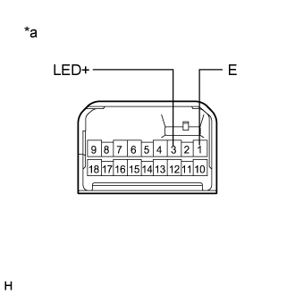 |
Check that the LED illuminates.
Apply auxiliary battery voltage to the power window regulator master switch assembly and check that the LED illuminates.
| Measurement Condition | Specified Condition |
| Auxiliary battery positive (+) → Terminal 3 (LED+) Auxiliary battery negative (-) → Terminal 1 (E) | LED illuminates |
| *a | Component without harness connected (Power Window Regulator Master Switch Assembly) |
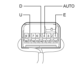 |
Check the switch function.
Reconnect the power window regulator master switch assembly connector.
Measure the voltage according to the value(s) in the table below.
| Tester Connection | Switch Condition | Specified Condition |
| 8 (U) - 1 (E) | Ignition switch ON, driver door power window regulator switch off | 11 to 14 V |
| 8 (U) - 1 (E) | Ignition switch ON, driver door power window regulator switch up (Auto up position) | Below 1 V |
| 8 (U) - 1 (E) | Ignition switch ON, driver door power window regulator switch up (Manual operation) | Below 1 V |
| 4 (AUTO) - 1 (E) | Ignition switch ON, driver door power window regulator switch off | 11 to 14 V |
| 4 (AUTO) - 1 (E) | Ignition switch ON, driver door power window regulator switch up (Auto up position) | Below 1 V |
| 4 (AUTO) - 1 (E) | Ignition switch ON, driver door power window regulator switch down (Auto down position) | Below 1 V |
| 5 (D) - 1 (E) | Ignition switch ON, driver door power window regulator switch off | 11 to 14 V |
| 5 (D) - 1 (E) | Ignition switch ON, driver door power window regulator switch down (Auto down position) | Below 1 V |
| 5 (D) - 1 (E) | Ignition switch ON, driver door power window regulator switch down (Manual operation) | Below 1 V |
| *a | Component with harness connected (Power Window Regulator Master Switch Assembly) |
| 2. INSPECT POWER WINDOW REGULATOR MASTER SWITCH ASSEMBLY (for RHD) |
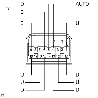 |
Check the switch function.
Turn the window lock switch off and operate the switches on the power window regulator master switch assembly.
Measure the resistance according to the value(s) in the table below.
| Tester Connection | Switch Condition | Specified Condition |
| 4 (AUTO) - 9 (E) | AUTO UP | Below 1 Ω |
| 1 (U) - 9 (E) | AUTO UP | Below 1 Ω |
| 1 (U) - 9 (E) | MANUAL UP | Below 1 Ω |
| 5 (D) - 9 (E) | MANUAL DOWN | Below 1 Ω |
| 4 (AUTO) - 9 (E) | AUTO DOWN | Below 1 Ω |
| 5 (D) - 9 (E) | AUTO DOWN | Below 1 Ω |
| Tester Connection | Switch Condition | Specified Condition |
| 6 (B) - 12 (U) | UP | Below 1 Ω |
| 9 (E) - 13 (D) | UP | Below 1 Ω |
| 9 (E) - 12 (U) | OFF | Below 1 Ω |
| 9 (E) - 13 (D) | OFF | Below 1 Ω |
| 9 (E) - 12 (U) | DOWN | Below 1 Ω |
| 6 (B) - 13 (D) | DOWN | Below 1 Ω |
| Tester Connection | Switch Condition | Specified Condition |
| 6 (B) - 16 (U) | UP | Below 1 Ω |
| 9 (E) - 15 (D) | UP | Below 1 Ω |
| 9 (E) - 15 (D) | OFF | Below 1 Ω |
| 9 (E) - 16 (U) | OFF | Below 1 Ω |
| 6 (B) - 15 (D) | DOWN | Below 1 Ω |
| 9 (E) - 16 (U) | DOWN | Below 1 Ω |
| Tester Connection | Switch Condition | Specified Condition |
| 6 (B) - 18 (U) | UP | Below 1 Ω |
| 9 (E) - 10 (D) | UP | Below 1 Ω |
| 9 (E) - 10 (D) | OFF | Below 1 Ω |
| 9 (E) - 18 (U) | OFF | Below 1 Ω |
| 6 (B) - 10 (D) | DOWN | Below 1 Ω |
| 9 (E) - 18 (U) | DOWN | Below 1 Ω |
| *a | Component without harness connected (Power Window Regulator Master Switch Assembly) |
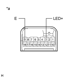 |
Check that the LED illuminates.
Apply auxiliary battery voltage to the power window regulator master switch assembly and check that the LED illuminates.
| Measurement Condition | Specified Condition |
| Auxiliary battery positive (+) → Terminal 3 (LED+) Auxiliary battery negative (-) → Terminal 9 (E) | LED illuminates |
| *a | Component without harness connected (Power Window Regulator Master Switch Assembly) |
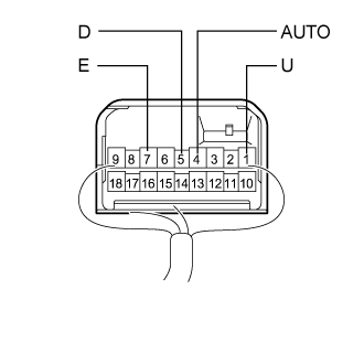 |
Check the switch function.
Reconnect the power window regulator master switch assembly connector.
Measure the voltage according to the value(s) in the table below.
| Tester Connection | Switch Condition | Specified Condition |
| 1 (U) - 9 (E) | Ignition switch ON, driver door power window regulator switch off | 11 to 14 V |
| 1 (U) - 9 (E) | Ignition switch ON, driver door power window regulator switch up (Auto up position) | Below 1 V |
| 1 (U) - 9 (E) | Ignition switch ON, driver door power window regulator switch up (Manual operation) | Below 1 V |
| 4 (AUTO) - 9 (E) | Ignition switch ON, driver door power window regulator switch off | 11 to 14 V |
| 4 (AUTO) - 9 (E) | Ignition switch ON, driver door power window regulator switch up (Auto up position) | Below 1 V |
| 4 (AUTO) - 9 (E) | Ignition switch ON, driver door power window regulator switch down (Auto down position) | Below 1 V |
| 5 (D) - 9 (E) | Ignition switch ON, driver door power window regulator switch off | 11 to 14 V |
| 5 (D) - 9 (E) | Ignition switch ON, driver door power window regulator switch down (Auto down position) | Below 1 V |
| 5 (D) - 9 (E) | Ignition switch ON, driver door power window regulator switch down (Manual operation) | Below 1 V |
| *a | Component with harness connected (Power Window Regulator Master Switch Assembly) |