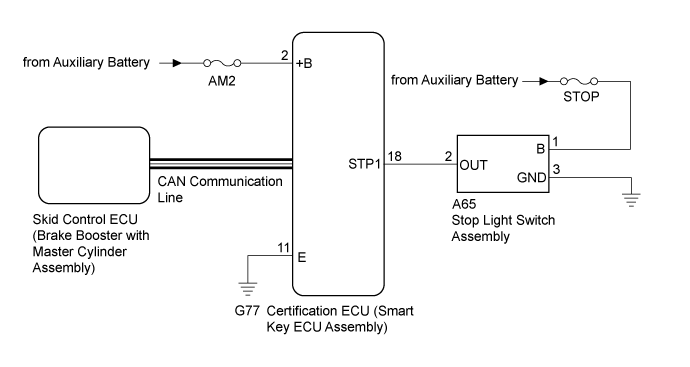
DTC B2284 Brake Signal Malfunction |
| DTC Code | DTC Detection Condition | Trouble Area | DTC Output Confirmation Operation |
| B2284 | The brake signal sent via direct line and the brake signal sent via CAN communication (1-trip detection logic*) do not match. |
| Connect the cable to the negative (-) auxiliary battery terminal, release the brake pedal and wait 20 seconds or more. Then depress the brake pedal for 20 seconds or more. |
| Vehicle Condition when Malfunction Detected | Fail-safe Function when Malfunction Detected |
With the electrical key transmitter sub-assembly in the cabin, even if an hybrid control system start operation is performed, the hybrid control system does not start (the multi-information display message (smart warning light) is not displayed). However, the hybrid control system can be started by turning the power switch on (ACC) and then pressing and holding it.
| - |
| DTC | Data List Item | Active Test Item |
| B2284 | Power Source Control
ABS/VSC/TRAC
| - |
| 1.READ VALUE USING INTELLIGENT TESTER (STOP LIGHT SWITCH ASSEMBLY) |
Connect the intelligent tester to the DLC3.
Turn the power switch on (IG).
Turn the intelligent tester on.
Enter the following menus: Body / Power Source Control / Data List.
Read the Data List according to the display on the intelligent tester.
| Tester Display | Measurement Item/Range | Normal Condition | Specified Condition |
| Stop Light Switch1 | Stop light switch1/ON or OFF | ON: Brake pedal depressed OFF: Brake pedal released |
|
|
| ||||
| OK | ||
 | ||
| ||
| 2.CHECK HARNESS AND CONNECTOR (POWER SOURCE) |
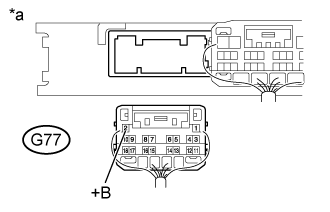 |
Disconnect the G77 connector from the certification ECU (smart key ECU assembly).
Measure the voltage according to the value(s) in the table below.
| Tester Connection | Condition | Specified Condition |
| G77-2 (+B) - Body ground | Power switch off | 11 to 14 V |
| *a | Rear view of wire harness connector (to Certification ECU (Smart Key ECU Assembly)) |
|
| ||||
| OK | |
 |
| 3.CHECK HARNESS AND CONNECTOR (GROUND) |
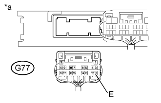 |
Measure the resistance according to the value(s) in the table below.
| Tester Connection | Condition | Specified Condition |
| G77-11 (E) - Body ground | Always | Below 1 Ω |
| *a | Rear view of wire harness connector (to Certification ECU (Smart Key ECU Assembly)) |
|
| ||||
| OK | |
|
| 4.CHECK HARNESS AND CONNECTOR (STOP LIGHT SWITCH ASSEMBLY - POWER SOURCE AND GROUND) |
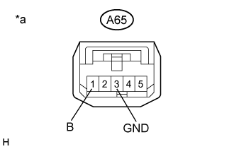 |
Disconnect the A65 stop light switch assembly connector.
Measure the voltage and resistance according to the value(s) in the table below.
| Tester Connection | Condition | Specified Condition |
| A65-1 (B) - A65-3 (GND) | Power switch off | 11 to 14 V |
| Tester Connection | Condition | Specified Condition |
| A65-3 (GND) - Body ground | Always | Below 1 Ω |
| *a | Front view of wire harness connector (to Stop Light Switch Assembly) |
|
| ||||
| OK | |
|
| 5.CHECK HARNESS AND CONNECTOR (CERTIFICATION ECU - STOP LIGHT SWITCH ASSEMBLY) |
Disconnect the G77 certification ECU (smart key ECU assembly) connector.
Disconnect the A65 stop light switch assembly connector.
Measure the resistance according to the value(s) in the table below.
| Tester Connection | Condition | Specified Condition |
| G77-18 (STP1) - A65-2 (OUT) | Always | Below 1 Ω |
| G77-18 (STP1) or A65-2 (OUT) - Body ground | Always | 10 kΩ or higher |
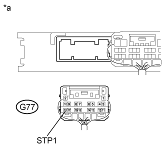 |
Reconnect the A65 stop light switch assembly connector.
Measure the voltage according to the value(s) in the table below.
| Tester Connection | Condition | Specified Condition |
| G77-18 (STP1) - Body ground | Brake pedal released | 1 V or less |
| Brake pedal depressed | 9 V or higher |
| *a | Rear view of wire harness connector (to Certification ECU (Smart Key ECU Assembly)) |
|
| ||||
| OK | ||
| ||
| ||

