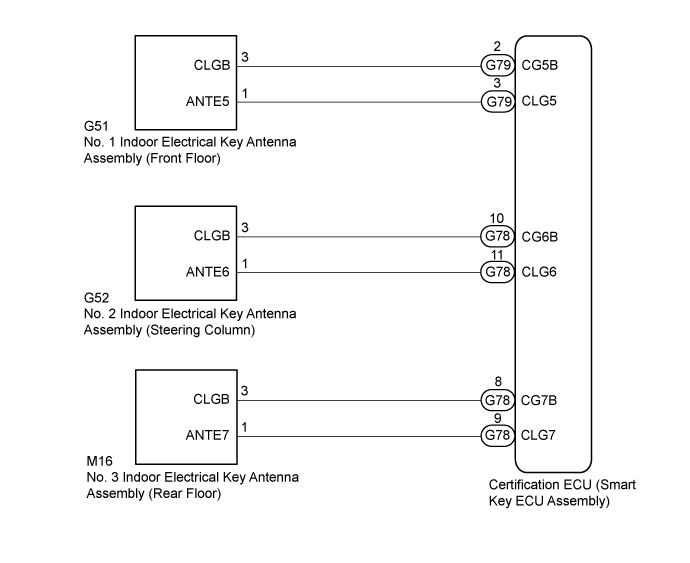
SMART ENTRY AND START SYSTEM (for Entry Function) > Room Oscillator does not Recognize Key |
| 1.CHECK ENTRY DOOR LOCK OPERATION |
Check that the entry lock and unlock functions operate for each door (Click here).
|
| ||||
| OK | |
 |
| 2.CHECK PUSH START FUNCTION |
 |
Remove the transmitter battery of the electrical key transmitter sub-assembly (Click here).
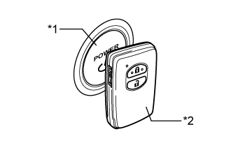
With the brake pedal depressed, face the logo side of the electrical transmitter sub-assembly towards the power switch, hold the transmitter near the power switch and then press the power switch.
When operating the power switch, check whether the hybrid system starts.
| *1 | Power Switch |
| *2 | Electrical Key Transmitter Sub-assembly |
|
| ||||
| OK | |
|
| 3.CHECK WAVE ENVIRONMENT |
Install the transmitter battery to the electrical key transmitter sub-assembly (Click here).
Bring the electrical key transmitter sub-assembly near the No. 1 indoor electrical key antenna assembly (front floor) and perform a smart entry and start system check (Click here).
Bring the electrical key transmitter sub-assembly near the No. 2 indoor electrical key antenna assembly (steering column) and perform a smart entry and start system check (Click here)
Bring the electrical key transmitter sub-assembly near the No. 3 indoor electrical key antenna assembly (rear floor) and perform a smart entry and start system check (Click here)
| Result | Proceed to |
| System cannot be operated | A |
| System can be operated | B |
|
| ||||
| A | |
|
| 4.CHECK KEY DIAGNOSTIC MODE |
Check the following antennas in the key diagnostic mode (Click here).
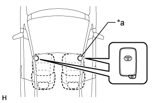 |
Check the No. 1 indoor electrical key antenna assembly (front floor).
| *a | Inspection Point |
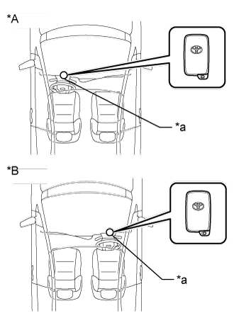 |
Check the No. 2 indoor electrical key antenna assembly (steering column).
| *A | for LHD |
| *B | for RHD |
| *a | Inspection Point |
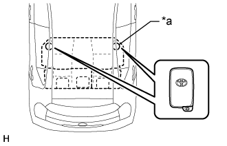 |
Check the No. 3 indoor electrical key antenna (rear floor):
| *a | Inspection Point |
| Result | Proceed to |
| Front floor operation check fails | A |
| Steering column operation check fails | B |
| Rear floor operation check fails | C |
| All operation checks are normal | D |
|
| ||||
|
| ||||
|
| ||||
| A | |
|
| 5.CHECK HARNESS AND CONNECTOR (NO. 1 INDOOR ELECTRICAL KEY ANTENNA ASSEMBLY - CERTIFICATION ECU) |
Disconnect the G51 No. 1 indoor electrical key antenna assembly (front floor) connector.
Disconnect the G79 certification ECU (smart key ECU assembly) connector.
Measure the resistance according to the value(s) in the table below.
| Tester Connection | Condition | Specified Condition |
| G51-1 (ANTE5) - G79-3 (CLG5) | Always | Below 1 Ω |
| G51-3 (CLGB) - G79-2 (CG5B) | Always | Below 1 Ω |
| G51-1 (ANTE5) or G79-3 (CLG5) - Body ground | Always | 10 kΩ or higher |
| G51-3 (CLGB) or G79-2 (CG5B) - Body ground | Always | 10 kΩ or higher |
|
| ||||
| OK | |
|
| 6.CHECK CERTIFICATION ECU (SMART KEY ECU ASSEMBLY) (OUTPUT TO NO. 1 INDOOR ELECTRICAL KEY ANTENNA) |
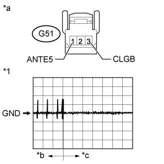 |
Disconnect the G51 No. 1 indoor electrical key antenna assembly (front floor) connector.
Connect the G79 certification ECU (smart key ECU assembly) connector.
Using an oscilloscope, check the waveform.
| Tester Connection | Switch Condition | Tool Setting | Specified Condition |
| G51-1 (ANTE5) - G51-3 (CLGB) | Procedure:
| 2 V/DIV., 500 ms/DIV. | Pulse generation (See waveform) |
| *1 | Waveform |
| *a | Front view of wire harness connector (to No. 1 Indoor Electrical Key Antenna [Front Floor]) |
| *b | Within approximately 30 seconds from when the door is closed |
| *c | After approximately 30 seconds from when the door is closed |
|
| ||||
| OK | |
|
| 7.REPLACE NO. 1 INDOOR ELECTRICAL KEY ANTENNA ASSEMBLY (FRONT FLOOR) |
Temporarily replace the No. 1 indoor electrical key antenna assembly (front floor) with a new or known good one (Click here).
| NEXT | |
|
| 8.CHECK KEY DIAGNOSTIC MODE |
Check the following antenna in the key diagnostic mode (Click here).
|
Check the No. 1 indoor electrical key antenna assembly (front floor).
When the electrical key transmitter sub-assembly is at the inspection point, check that the wireless door lock buzzer sounds.
| *a | Inspection Point |
|
| ||||
| OK | ||
 | ||
| ||
| 9.CHECK HARNESS AND CONNECTOR (NO. 2 INDOOR ELECTRICAL KEY ANTENNA ASSEMBLY - CERTIFICATION ECU) |
Disconnect the G52 No. 2 indoor electrical key antenna assembly (steering column) connector.
Disconnect the G78 certification ECU (smart key ECU assembly) connector.
Measure the resistance according to the value(s) in the table below.
| Tester Connection | Condition | Specified Condition |
| G52-1 (ANTE6) - G78-11 (CLG6) | Always | Below 1 Ω |
| G52-3 (CLGB) - G78-10 (CG6B) | Always | Below 1 Ω |
| G52-1 (ANTE6) or G78-11 (CLG6) - Body ground | Always | 10 kΩ or higher |
| G52-3 (CLGB) or G78-10 (CG6B) - Body ground | Always | 10 kΩ or higher |
|
| ||||
| OK | |
|
| 10.CHECK CERTIFICATION ECU (SMART KEY ECU ASSEMBLY) (OUTPUT TO NO. 2 INDOOR ELECTRICAL KEY ANTENNA) |
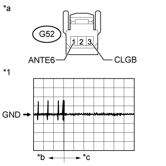 |
Disconnect the G52 No. 2 indoor electrical key antenna assembly (steering column) connector.
Connect the G78 certification ECU (smart key ECU assembly) connector.
Using an oscilloscope, check the waveform.
| Tester Connection | Switch Condition | Tool Setting | Specified Condition |
| G52-1 (ANTE6) - G52-3 (CLGB) | Procedure:
| 2 V/DIV., 500 ms/DIV. | Pulse generation (See waveform) |
| *1 | Waveform |
| *a | Front view of wire harness connector (to No. 2 Indoor Electrical Key Antenna [Steering Column]) |
| *b | Within approximately 30 seconds from when the door is closed |
| *c | After approximately 30 seconds from when the door is closed |
|
| ||||
| OK | |
|
| 11.REPLACE NO. 2 INDOOR ELECTRICAL KEY ANTENNA ASSEMBLY (STEERING COLUMN) |
Temporarily replace the No. 2 indoor electrical key antenna assembly (steering column) with a new or known good one (Click here).
| NEXT | |
|
| 12.CHECK KEY DIAGNOSTIC MODE |
Check the following antenna in the key diagnostic mode (Click here).
|
Check the No. 2 indoor electrical key antenna assembly (steering column).
When the electrical key transmitter sub-assembly is at the inspection point, check that the wireless door lock buzzer sounds.
| *A | for LHD |
| *B | for RHD |
| *a | Inspection Point |
|
| ||||
| OK | ||
| ||
| ||
| 13.CHECK HARNESS AND CONNECTOR (NO. 3 INDOOR ELECTRICAL KEY ANTENNA ASSEMBLY - CERTIFICATION ECU) |
Disconnect the M16 No. 3 indoor electrical key antenna assembly (rear floor) connector.
Disconnect the G78 certification ECU (smart key ECU assembly) connector.
Measure the resistance according to the value(s) in the table below.
| Tester Connection | Condition | Specified Condition |
| M16-1 (ANTE7) - G78-9 (CLG7) | Always | Below 1 Ω |
| M16-3 (CLGB) - G78-8 (CG7B) | Always | Below 1 Ω |
| M16-1 (ANTE7) or G78-9 (CLG7) - Body ground | Always | 10 kΩ or higher |
| M16-3 (CLGB) or G78-8 (CG7B) - Body ground | Always | 10 kΩ or higher |
|
| ||||
| OK | |
|
| 14.CHECK CERTIFICATION ECU (SMART KEY ECU ASSEMBLY) (OUTPUT TO NO. 3 INDOOR ELECTRICAL KEY ANTENNA) |
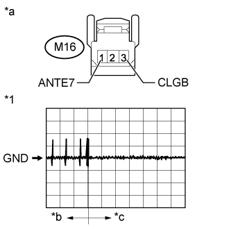 |
Disconnect the M16 No. 3 indoor electrical key antenna assembly (rear floor) connector.
Connect the G78 certification ECU (smart key ECU assembly) connector.
Using an oscilloscope, check the waveform.
| Tester Connection | Switch Condition | Tool Setting | Specified Condition |
| M16-1 (ANTE7) - M16-3 (CLGB) | Procedure:
| 2 V/DIV., 500 ms/DIV. | Pulse generation (See waveform) |
| *1 | Waveform |
| *a | Front view of wire harness connector (to No. 3 Indoor Electrical Key Antenna [Rear Floor]) |
| *b | Within approximately 30 seconds from when the door is closed |
| *c | After approximately 30 seconds from when the door is closed |
|
| ||||
| OK | |
|
| 15.REPLACE NO. 3 INDOOR ELECTRICAL KEY ANTENNA ASSEMBLY (REAR FLOOR) |
Temporarily replace the No. 3 indoor electrical key antenna assembly (rear floor) with a new or known good one (Click here).
| NEXT | |
|
| 16.CHECK SELF DIAGNOSTIC MODE |
Check the following antenna in the key diagnostic mode (Click here).
|
Check the No. 3 indoor electrical key antenna assembly (rear floor).
When the electrical key transmitter sub-assembly is at the inspection point, check that the wireless door lock buzzer sounds.
| *a | Inspection Point |
|
| ||||
| OK | ||
| ||
| ||

