Home › Vehicle Exterior › DOOR / HATCH › HOOD LOCK CONTROL CABLE ASSEMBLY

HOOD LOCK CONTROL CABLE ASSEMBLY > INSTALLATION

for Preparation Click here


1. INSTALL HOOD LOCK CONTROL CABLE ASSEMBLY (for LHD)
  1. Pass the hood lock control cable assembly into the engine compartment.

  1. Pass the cable through the upper radiator support.

  1. Engage the hood lock control cable assembly to the 3 clamps and grommet to connect the hood lock control cable assembly.


2. INSTALL HOOD LOCK CONTROL CABLE ASSEMBLY (for RHD)
  1. Pass the hood lock control cable assembly into the engine compartment.

  1. Pass the cable through the upper radiator support.

  1. Engage the hood lock control cable assembly to the 3 clamps and grommet to connect the hood lock control cable assembly.


3. INSTALL HOOD LOCK CONTROL LEVER SUB-ASSEMBLY
  1. Connect the hood lock control cable assembly to the hood lock control lever sub-assembly.

  1. Engage the 3 claws to install the hood lock control lever sub-assembly.


4. INSTALL HOOD LOCK ASSEMBLY
  1. Apply MP grease to the sliding areas of the hood lock assembly.

  1. Connect the hood lock control cable.

  1. Install the hood lock with the 3 bolts.

    Torque:
    7.5 N*m{ 76 kgf*cm , 66 in.*lbf }


5. INSTALL COWL SIDE TRIM BOARD LH (for LHD)
  1. Engage the clip.

  1. Install the cowl side trim board with the clip.


6. INSTALL FRONT DOOR SCUFF PLATE LH (for LHD)
  1. Engage the 8 claws to install the front door scuff plate.


7. INSTALL COWL SIDE TRIM BOARD RH (for RHD)

HINT:
Use the same procedure for the RH side and LH side .


8. INSTALL FRONT DOOR SCUFF PLATE RH (for RHD)

HINT:
Use the same procedure for the RH side and LH side .


9. INSPECT HOOD SUB-ASSEMBLY


  1. Check that the clearance measurements of areas "a" through "f" are within each standard range.
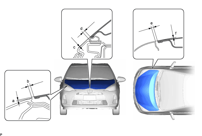

    B301498E02


    Standard Clearance 
    Area
    Measurement
    Area
    Measurement
    a
    -0.85 to 3.15 mm (-0.0335 to 0.124 in.)
    b
    1.65 to 5.65 mm (0.065 to 0.222 in.)
    c
    -1.85 to 2.15 mm (-0.0728 to 0.0847 in.)
    d
    2.35 to 6.35 mm (0.0925 to 0.25 in.)
    e
    2.0 to 5.0 mm (0.0787 to 0.197 in.)
    f
    -1.5 to 1.5 mm (-0.0591 to 0.0591 in.)


10. ADJUST HOOD SUB-ASSEMBLY


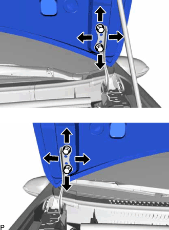
  1. Horizontally and vertically adjust the hood.


      B301499
    1. Loosen the 4 hinge bolts of the hood.

    2. Adjust the clearance between the hood and front fender by moving the hood.

    3. Tighten the 4 hinge bolts after the adjustment.

      Torque:
      13 N*m{ 133 kgf*cm , 10 ft.*lbf }


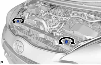
  1. Adjust the height of the front end of the hood using the cushion rubbers.


      B297000
    1. Adjust the 2 cushion rubbers so that the heights of the hood and fender are aligned.

      HINT:
      Raise or lower the front end of the hood by turning the 2 cushion rubbers.


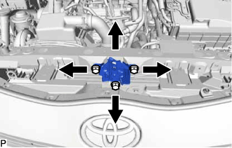
  1. Adjust the hood lock.


      B301500
    1. Loosen the 3 bolts.

    2. Tighten the bolts after adjustment.

      Torque:
      7.5 N*m{ 76 kgf*cm , 66 in.*lbf }

    3. Check that the striker can engage with the hood lock smoothly.


11. INSTALL FRONT FENDER LINER LH (for LHD)

HINT:
Use the same procedure for the RH side and LH side


12. INSTALL FRONT WHEEL LH (for LHD)

Torque:
103 N*m{ 1049 kgf*cm , 76 ft.*lbf }


13. INSTALL FRONT FENDER LINER RH (for RHD)
  1. Install the front fender liner RH with 4 new grommets.

  1. Install the 7 clips

  1. Install the 3 screws and front fender liner RH.


14. INSTALL FRONT WHEEL RH (for RHD)

Torque:
103 N*m{ 1049 kgf*cm , 76 ft.*lbf }