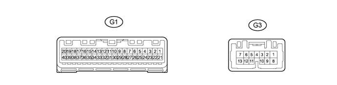
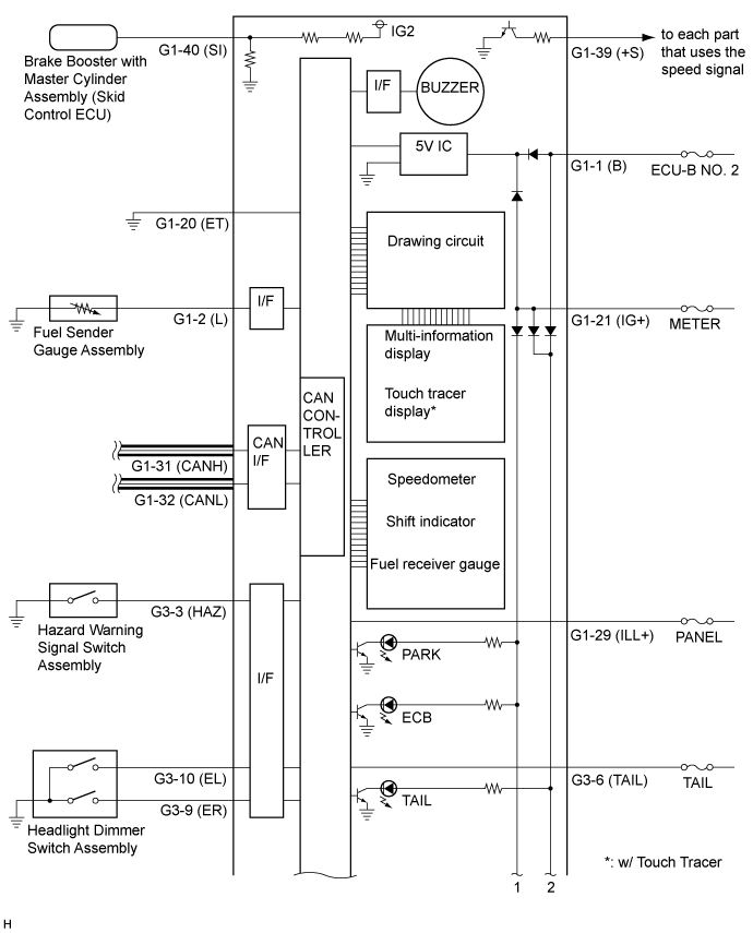
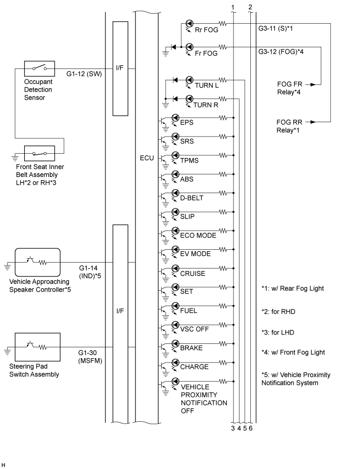
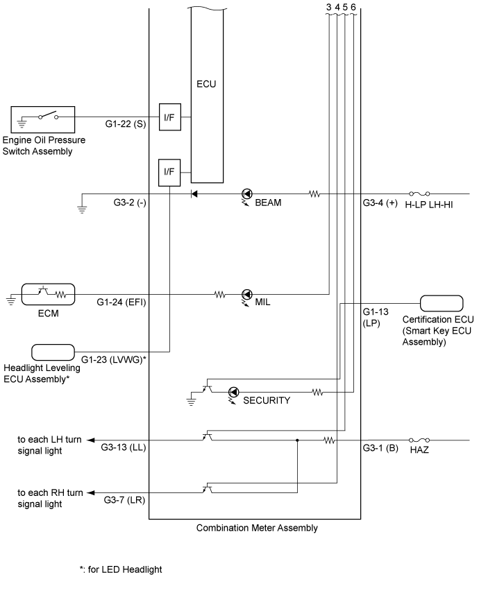
Terminal No. (Symbol)
| Wiring Color
| Terminal Description
| Condition
| Specified Condition
|
G1-1 (B) - Body ground
| L - Body ground
| Battery
| Power switch off
| 11 to 14 V
|
G1-2 (L) - Body ground
| V - Body ground
| Fuel signal
| Power switch on (IG), fuel level not low
| 4 V or less
|
Power switch on (IG), fuel level low
| 4 to 14 V
|
G1-12 (SW) - Body ground
| BE - Body ground
| Front passenger seat belt buckle switch signal
| Power switch on (IG), front passenger seat occupied, and front passenger seat belt unfastened
| Below 1 Ω
|
Power switch on (IG), front passenger seat occupied, and front passenger seat belt fastened
| 10 kΩ or higher
|
G1-13 (LP) - Body ground
| LG - Body ground
| Security indicator light signal
| Power switch on (IG), security indicator light off
| Below 1 V
|
Power switch on (IG), security indicator light blinks
| 3.5 to 8.5 V ←→ 11 to 14 V
|
G1-14 (IND) - Body ground*4
| L - Body ground
| Vehicle approaching speaker switch signal
| Power switch on (IG), vehicle proximity notification off indicator light off
| 11 to 14 V
|
Power switch on (IG), vehicle proximity notification off indicator light on
| Below 1 V
|
G1-20 (ET) - Body Ground
| BR - Body ground
| Ground
| Always
| Below 1 Ω
|
G1-21 (IG+) - Body ground
| B - Body ground
| Power switch signal
| Power switch off
| Below 1 V
|
Power switch on (IG)
| 11 to 14 V
|
G1-22 (S) - Body ground
| GR - Body ground
| Oil pressure signal
| Engine started
| 4 to 6 V
|
Engine not started
| Below 1 V
|
G1-23 (LVWG)*3 - Body ground
| W - Body ground
| Headlight leveling warning light signal
| Power switch on (IG), headlight leveling warning light off
| Below 1 V
|
Power switch on (IG), headlight leveling warning light on
| 11 to 14 V
|
G1-24 (EFI) - Body ground
| B - Body ground
| MIL (Check engine warning light) signal
| Power switch on (IG), MIL off
| 11 to 14 V
|
Power switch on (IG), MIL on
| Below 1 V
|
G1-29 (ILL+) - Body ground
| R - Body ground
| Illumination signal
| Light control switch off
| Below 1 V
|
Light control switch on TAIL or HEAD position
| 11 to 14 V
|
G1-30 (MSFM) - Body ground
| W - Body ground
| Multi-information switch (steering pad switch assembly) signal
| Power switch on
| Pulse generation
|
G1-31 (CANH) - Body ground
| G - Body ground
| CAN communication line
| -
| -
|
G1-32 (CANL) - Body ground
| W - Body ground
| CAN communication line
| -
| -
|
G1-39 (+S) - Body ground
| SB - Body ground
| Speed signal for other system (Output)
| Power switch on (IG), wheel being rotated
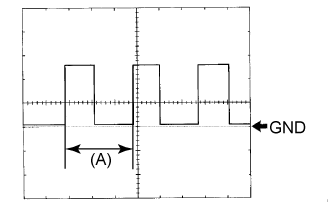
| Pulse generation (See waveform 1)
|
G1-40 (SI) - Body ground
| V - Body ground
| Speed signal for other system (Input)
| Power switch on (IG), wheel being rotated
| Pulse generation (See waveform 1)
|
G3-1 (B) - Body ground
| R - Body ground
| Battery
| Power switch off
| 11 to 14 V
|
G3-2 (-) - Body ground
| W-B - Body ground
| Ground
| Always
| Below 1 Ω
|
G3-3 (HAZ) - Body ground
| B - Body ground
| Hazard warning switch signal
| Power switch on (IG), hazard warning switch not pressed
| 11 to 14 V
|
Power switch on (IG), hazard warning switch pressed
| Below 1 V
|
G3-4 (+) - Body ground
| GR - Body ground
| High beam signal
| Power switch on (IG), high beam off
| Below 1 V
|
Power switch on (IG), high beam on
| 11 to 14 V
|
G3-6 (TAIL) - Body ground
| R - Body ground
| Tail indicator light signal
| Power switch on (IG), tail indicator light off
| Below 1 V
|
Power switch on (IG), tail indicator light on
| 11 to 14 V
|
G3-7 (LR) - Body ground
| G - Body ground
| RH turn indicator light signal
| RH turn indicator light off
| 11 to 14 V
|
RH turn indicator light blinks
| 11 to 14 V ←→ Below 1 V
|
G3-9 (ER) - Body ground
| B - Body ground
| RH turn signal switch signal
| Power switch on (IG), RH turn signal switch off
| 11 to 14 V
|
Power switch on (IG), RH turn signal switch on
| Below 1 V
|
G3-10 (EL) - Body ground
| Y - Body ground
| LH turn signal switch signal
| Power switch on (IG), LH turn signal switch off
| 11 to 14 V
|
Power switch on (IG), LH turn signal switch on
| Below 1 V
|
G3-11 (S)*1 - Body ground
| SB - Body ground
| Rear fog indicator light signal
| Power switch on (IG), rear fog indicator light off
| Below 1 V
|
Power switch on (IG), rear fog indicator light on
| 11 to 14 V
|
G3-12 (FOG)*2 - Body ground
| BE - Body ground
| Front fog indicator light signal
| Power switch on (IG), front fog indicator light off
| Below 1 V
|
Power switch on (IG), front fog indicator light on
| 11 to 14 V
|
G3-13 (LL) - Body ground
| LG - Body ground
| LH turn indicator light signal
| LH turn indicator light off
| 11 to 14 V
|
LH turn indicator light blinks
| 11 to 14 V ←→ Below 1 V
|