Home › Engine / Hybrid System › 1NZ-FXE ENGINE CONTROL › ECM

ECM > INSTALLATION

for Preparation Click here


1. INSTALL ECM (for LHD)
  1. Install the No. 1 ECM bracket and No. 2 ECM bracket with the 4 screws.

    Torque:
    3.0 N*m{ 31 kgf*cm , 27 in.*lbf }

  1. Install the nut.

    Torque:
    8.0 N*m{ 82 kgf*cm , 71 in.*lbf }

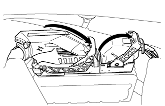
  1. Install the ECM with the bolt and nut.

    Torque:
    8.0 N*m{ 82 kgf*cm , 71 in.*lbf }


    A275536
  1. Connect the 2 ECM connectors and lower the 2 levers.

    NOTICE:
    1. When connecting the connectors, make sure that dirt, water or other foreign matter does not get caught between the connectors and other parts.
    2. Make sure that the 2 levers are securely locked.


2. INSTALL OUTER COWL TOP PANEL SUB-ASSEMBLY (for LHD)


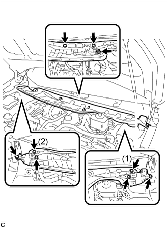
    C250015E01
  1. Install the outer cowl top panel sub-assembly with the 8 bolts and nut.

    Torque:
    Bolt:
    7.0 N*m{ 71 kgf*cm , 62 in.*lbf }
    Nut:
    12 N*m{ 122 kgf*cm , 9 ft.*lbf }

    NOTICE:
    Tighten the 2 bolts (1) and (2) first, and then tighten the rest of the bolts and nut.

  1. Engage the clamp to install the wire harness.


3. INSTALL FRONT NO. 1 VENTILATOR SEAL (for LHD)
  1. Engage the clamp to install the front No. 1 ventilator seal to the outer cowl top panel sub-assembly.


4. INSTALL FRONT AIR SHUTTER SEAL (for LHD)
  1. Engage the clamp to install the front air shutter seal to the outer cowl top panel sub-assembly.


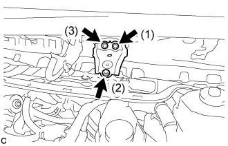
5. INSTALL INNER COWL TOP TO COWL BRACE (for LHD)


    C250011E01
  1. Install the inner cowl top to cowl brace to the outer cowl top panel sub-assembly with the 3 bolts.

    Torque:
    7.0 N*m{ 71 kgf*cm , 62 in.*lbf }

    NOTICE:
    Tighten the 3 bolts in the order shown in the illustration.


6. INSTALL WINDSHIELD WIPER MOTOR AND LINK ASSEMBLY (for LHD)
(Click here).


7. INSTALL ECM (for RHD)
  1. Install the No. 1 ECM bracket and No. 2 ECM bracket with the 4 screws.

    Torque:
    3.0 N*m{ 31 kgf*cm , 27 in.*lbf }

  1. Install the ECM with the bolt and nut.

    Torque:
    8.0 N*m{ 82 kgf*cm , 71 in.*lbf }


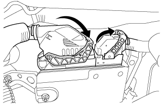
    A275537
  1. Connect the 2 ECM connectors and lower the 2 levers.

    NOTICE:
    1. When connecting the connectors, make sure that dirt, water or other foreign matter does not get caught between the connectors and other parts.
    2. Make sure that the 2 levers are securely locked.


8. CONNECT CABLE TO NEGATIVE AUXILIARY BATTERY TERMINAL

NOTICE:
When disconnecting the cable, some systems need to be initialized after the cable is reconnected (Click here).


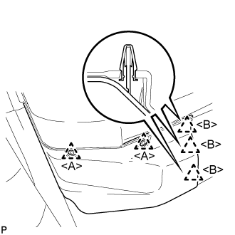
9. INSTALL FRONT FLOOR COVER RH
  1. Engage the 3 guides.


    B301488E01
  1. Engage the clip <B> to install the front floor cover RH.

  1. Install the 2 clips <A>.


10. PERFORM INITIALIZATION

HINT:
Initialization cannot be completed by only disconnecting and reconnecting the cable of the negative (-) auxiliary battery terminal.

  1. Perform Initialization when replacing the ECM .