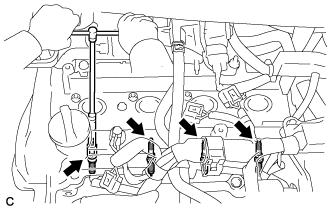
 |
Using a 16 mm spark plug wrench, remove the 4 spark plugs.
ENGINE UNIT > DISASSEMBLY |
| 1. REMOVE SPARK PLUG |
|
Using a 16 mm spark plug wrench, remove the 4 spark plugs.
| 2. REMOVE OIL FILLER CAP SUB-ASSEMBLY |
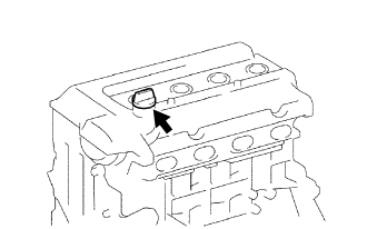 |
Remove the oil filler cap sub-assembly from the cylinder head cover.
| 3. REMOVE OIL FILLER CAP GASKET |
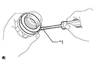 |
Using a screwdriver, remove the oil filler cap gasket from the oil filler cap.
| *1 | Protective Tape |
| 4. REMOVE ENGINE OIL LEVEL DIPSTICK GUIDE |
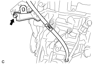 |
Remove the bolt and engine oil level dipstick guide.
Remove the O-ring from the engine oil level dipstick guide.
| 5. REMOVE CAMSHAFT POSITION SENSOR |
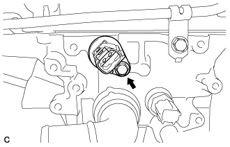 |
Remove the bolt and camshaft position sensor.
| 6. REMOVE CAMSHAFT TIMING OIL CONTROL VALVE ASSEMBLY |
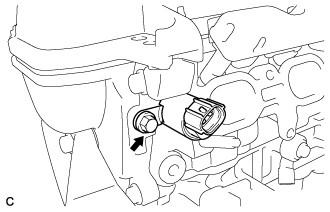 |
Remove the bolt and camshaft timing oil control valve assembly.
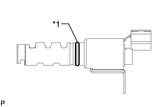 |
Remove the O-ring from the camshaft timing oil control valve assembly.
| 7. REMOVE KNOCK CONTROL SENSOR |
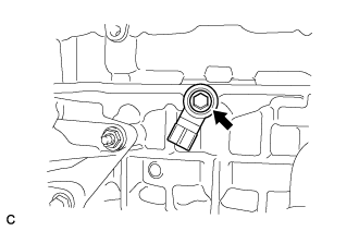 |
Remove the bolt and knock control sensor.
| 8. REMOVE ENGINE COOLANT TEMPERATURE SENSOR |
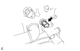 |
Using a 19 mm union nut wrench, remove the engine coolant temperature sensor and gasket.
| 9. REMOVE ENGINE OIL PRESSURE SWITCH ASSEMBLY |
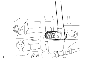 |
Using a 24 mm deep socket wrench, remove the engine oil pressure switch assembly.
| 10. REMOVE OIL FILTER SUB-ASSEMBLY |
Using SST, remove the oil filter.
| 11. REMOVE CRANKSHAFT POSITION SENSOR |
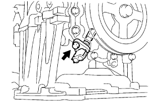 |
Remove the bolt and crankshaft position sensor.
| 12. REMOVE WATER INLET WITH THERMOSTAT SUB-ASSEMBLY |
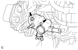 |
Remove the 2 bolts and water inlet with thermostat sub-assembly.
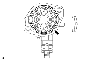 |
Remove the gasket from the water inlet with thermostat sub-assembly.
| 13. REMOVE ENGINE WATER PUMP ASSEMBLY |
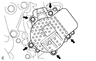 |
Remove the 5 bolts and engine water pump assembly.
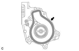 |
Remove the gasket from the engine water pump assembly.
| 14. REMOVE WATER INLET HOUSING |
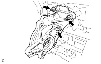 |
Remove the bolt, 2 nuts and water inlet housing.
Remove the gasket.
| 15. REMOVE ENGINE MOUNTING BRACKET RH |
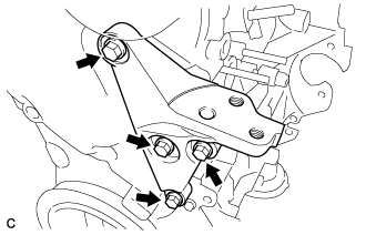 |
Remove the 4 bolts and engine mounting bracket RH.
| 16. REMOVE VENTILATION VALVE SUB-ASSEMBLY |
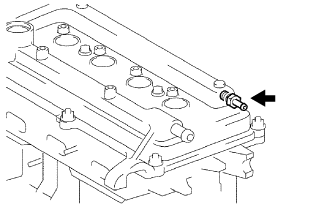 |
Using a 19 mm deep socket wrench, remove the ventilation valve sub-assembly from the cylinder head cover sub-assembly.
| 17. REMOVE CYLINDER HEAD COVER SUB-ASSEMBLY |
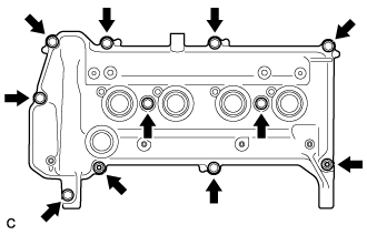 |
Remove the 9 bolts, 2 seal washers, 2 nuts and cylinder head cover sub-assembly.
Remove the gasket from the cylinder head cover sub-assembly.
| 18. REMOVE CRANKSHAFT DAMPER SUB-ASSEMBLY |
Set the No. 1 cylinder to TDC/compression.
Turn the crankshaft damper until its notch and timing mark "0" of the timing chain cover are aligned.
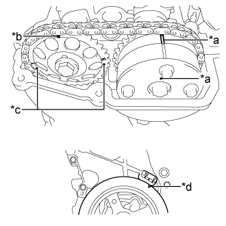 |
Check that the timing marks on both the camshaft timing sprocket and the camshaft timing gear are facing upward as shown in the illustration.
| *a | Timing Mark |
| *b | Timing Mark (Rectangle) |
| *c | Mark (Circle) |
| *d | Timing Notch |
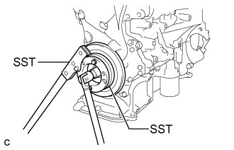 |
Using SST, hold the crankshaft damper sub-assembly in place and loosen the bolt.
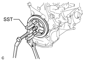 |
Using SST, remove the crankshaft damper sub-assembly and bolt.
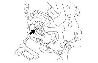 |
Remove the crankshaft straight pin.
| 19. REMOVE TIMING CHAIN COVER |
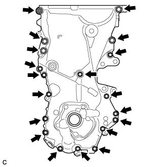 |
Remove the 18 bolts, nut and 2 wire harness clamp brackets.
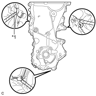 |
Remove the timing chain cover by prying between the timing chain cover and oil pan, cylinder head or cylinder block with a screwdriver.
| *1 | Protective Tape |
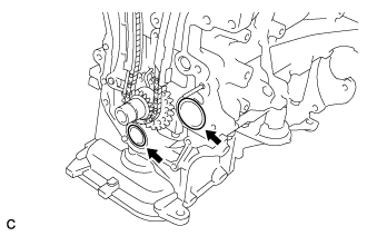 |
Remove the 2 O-rings from the cylinder block and oil pan.
| 20. REMOVE SCREW PLUG |
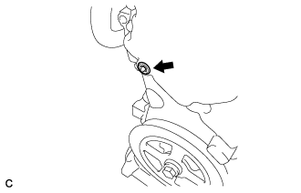 |
Using a 8 mm hexagon socket wrench, remove the screw plug.
| 21. REMOVE OIL PUMP SEAL |
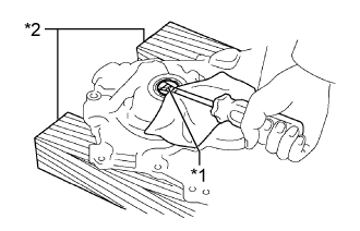 |
Using a screwdriver and wooden block, remove the oil pump seal.
| *1 | Protective Tape |
| *2 | Wooden Block |
| 22. REMOVE NO. 1 CHAIN TENSIONER ASSEMBLY |
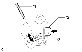 |
Turn the stopper plate of the No. 1 chain tensioner assembly clockwise and push in the plunger with the lock released.
| *1 | Hexagon Wrench |
| *2 | Plunger |
| *3 | Stopper Plate |
Turn the stopper plate of the No. 1 chain tensioner assembly counterclockwise and insert a hexagon wrench into the hole in the stopper plate to lock with the plunger pushed in.
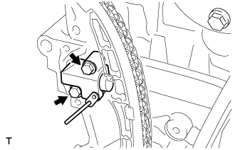 |
Remove the 2 bolts and No. 1 chain tensioner assembly.
| 23. REMOVE CHAIN TENSIONER SLIPPER |
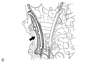 |
Remove the chain tensioner slipper.
| 24. REMOVE NO. 1 CHAIN VIBRATION DAMPER |
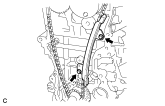 |
Remove the 2 bolts and No. 1 chain vibration damper.
| 25. REMOVE CHAIN SUB-ASSEMBLY |
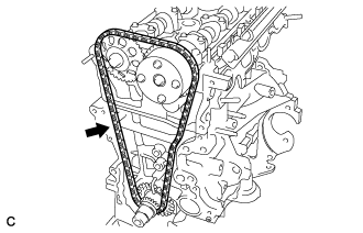 |
Remove the chain sub-assembly.
| 26. REMOVE FUEL DELIVERY PIPE |
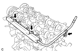 |
Remove the 3 bolts and fuel delivery pipe.
| 27. REMOVE FUEL DELIVERY SPACER |
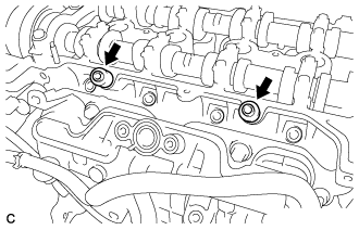 |
Remove the 2 fuel delivery spacers from the cylinder head.
| 28. REMOVE INJECTOR VIBRATION INSULATOR |
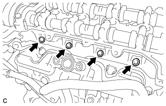 |
Remove the 4 injector vibration insulators from the cylinder head.
| 29. REMOVE FUEL INJECTOR ASSEMBLY |
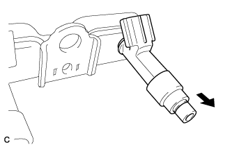 |
Pull the 4 fuel injector assemblies out of the fuel delivery pipe.
 | Pull |
Remove the O-ring from each fuel injector.
For reinstallation, attach a tag or label to each injector shaft.
| 30. REMOVE NO. 2 CAMSHAFT |
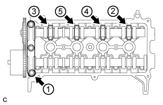 |
Using several steps, uniformly loosen and remove the 11 bolts in the sequence shown in the illustration. Then remove the No. 1 camshaft bearing cap and 4 No. 2 camshaft bearing caps.
| 31. REMOVE CAMSHAFT TIMING GEAR OR SPROCKET |
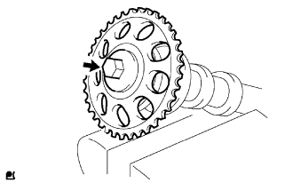 |
Clamp the No. 2 camshaft in a vise.
Remove the bolt and camshaft timing gear or sprocket.
| 32. REMOVE CAMSHAFT |
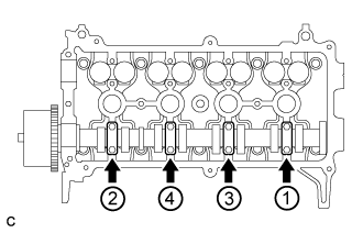 |
Using several steps, uniformly loosen and remove the 8 bolts in the sequence shown in the illustration. Then remove the 4 No. 2 camshaft bearing caps.
| 33. INSPECT CAMSHAFT TIMING GEAR ASSEMBLY |
Check the camshaft timing gear assembly lock.
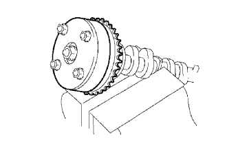 |
Clamp the camshaft in a vise, and make sure that the camshaft timing gear assembly does not rotate.
Release the lock pin.
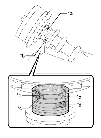 |
Cover the 4 oil paths of the cam journal with vinyl tape as shown in the illustration.
| *a | Retard Side Path |
| *b | Advance Side Path |
| *c | Open |
| *d | Close |
 | Rubber Piece |
 | Vinyl Tape |
Prick a hole in the tape placed on the advance side path. Prick a hole in the tape placed on the retard side path, on the opposite side to that of the advance side path, as shown in the illustration.
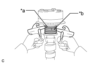 |
Apply approximately 150 kPa (1.5 kgf/cm2, 22 psi) of air pressure to the 2 paths (the advance side path and the retard side path).
| *a | Advance Side Path |
| *b | Retard Side Path |
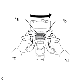 |
Make sure that the camshaft timing sprocket turns in the retard direction when reducing the air pressure applied to the advance side path.
| *a | Advance Side Path |
| *b | Retard Side Path |
| *c | Decompress |
| *d | Hold Pressure |
When the camshaft timing sprocket moves to the most retarded position, release the air pressure from the advance side path, and then release the air pressure from the retard side path.
| 34. REMOVE CAMSHAFT TIMING GEAR ASSEMBLY |
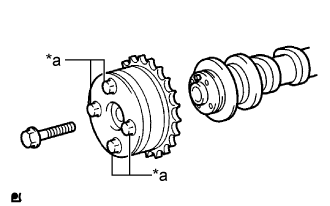 |
Remove the bolt and camshaft timing gear assembly.
| *a | Do Not Remove |
| 35. REMOVE CYLINDER HEAD SUB-ASSEMBLY |
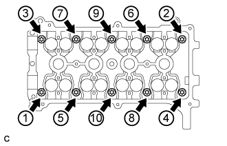 |
Using several steps, uniformly loosen and remove the 10 cylinder head bolts and 10 washers with an 8 mm bi-hexagon wrench in the sequence shown in the illustration.
Remove the cylinder head sub-assembly.
| 36. REMOVE CYLINDER HEAD GASKET |
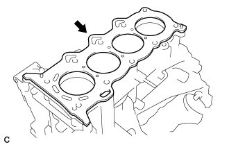 |
Remove the cylinder head gasket from the cylinder block.
| 37. REMOVE OIL FILTER UNION |
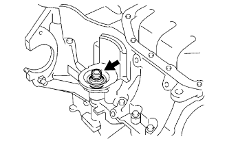 |
Using a 12 mm hexagon socket wrench, remove the oil filter union.
| 38. REMOVE NO. 2 OIL PAN SUB-ASSEMBLY |
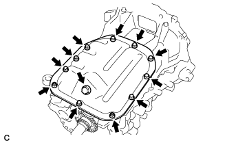 |
Remove the oil pan drain plug and gasket.
Remove the 9 bolts and 2 nuts.
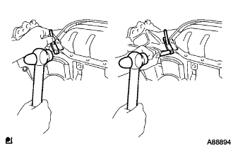 |
Insert the blade of an oil pan seal cutter between the oil pan and No. 2 oil pan sub-assembly, cut the sealer and remove the No. 2 oil pan sub-assembly.
| 39. REMOVE OIL STRAINER SUB-ASSEMBLY |
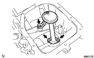 |
Remove the bolt, 2 nuts, oil strainer sub-assembly and gasket.
| 40. REMOVE OIL PAN SUB-ASSEMBLY |
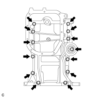 |
Loosen and remove the 13 bolts uniformly in several steps.
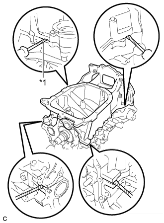 |
Using a screwdriver, remove the oil pan sub-assembly by prying between the cylinder block and oil pan sub-assembly.
| *1 | Protective Tape |
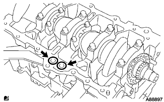 |
Remove the 2 O-rings from the cylinder block.
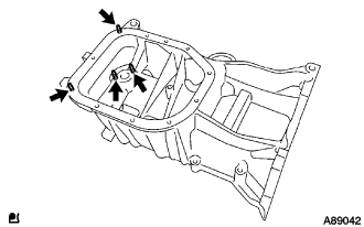 |
Using an E5 "TORX" socket wrench, remove the 4 stud bolts.
| 41. REMOVE REAR ENGINE OIL SEAL |
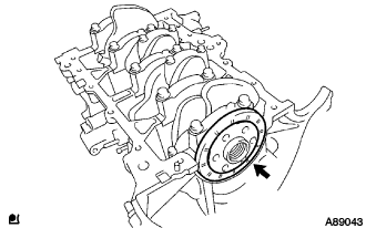 |
Remove the rear engine oil seal.