 |
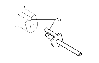
Align the concave part of the cylinder block with the bracket of a new oil jet, then tap in the oil jet (the service part).
| *a | Align |
- NOTICE:
- Do not tap the tip of the oil jet.
CYLINDER BLOCK > REASSEMBLY |
| 1. INSTALL OIL JET |
|
Align the concave part of the cylinder block with the bracket of a new oil jet, then tap in the oil jet (the service part).
| *a | Align |
| 2. INSTALL WATER BY-PASS HOSE UNION |
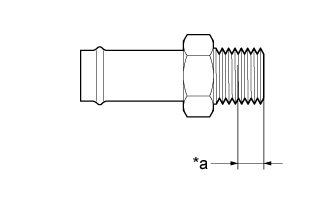 |
Apply adhesive as shown in the illustration.
| *a | 6.0 mm (0.236 in.) |
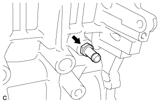 |
Using a 17 mm deep socket wrench, install the water by-pass hose union to the cylinder block.
| 3. INSTALL CRANKSHAFT BEARING |
Clean the main journal and both surfaces of the crankshaft bearing.
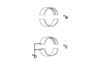 |
Mass production parts do not have claws. If reusing mass production parts, measure the clearance of both sides with the crankshaft bearings in the center of the crankshaft bearing caps.
| *a | Mass Production Part |
| *b | Claw |
| *c | Service Part |
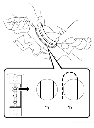 |
Install the 5 upper crankshaft bearings to the cylinder block as shown in the illustration.
| *a | Correct |
| *b | Incorrect |
Install the 5 lower crankshaft bearings onto the crankshaft bearing cap.
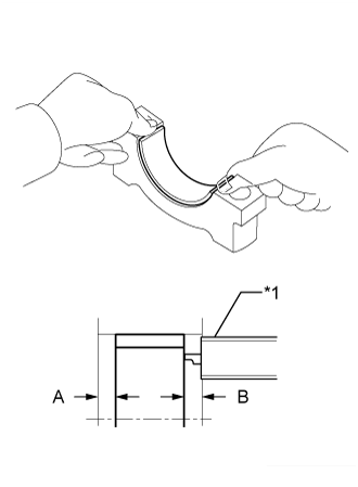 |
Using a vernier caliper, measure the distance between the crankshaft bearing caps edge and the lower crankshaft bearings edge.
| *1 | Vernier Caliper |
| 4. INSTALL UPPER CRANKSHAFT THRUST WASHER |
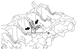 |
Install the 2 upper crankshaft thrust washers onto the No. 3 journal position of the cylinder block with the oil grooves facing outward.
| *a | Oil Groove |
| 5. INSTALL CRANKSHAFT |
Apply engine oil to the upper crankshaft bearings and install the crankshaft onto the cylinder block.
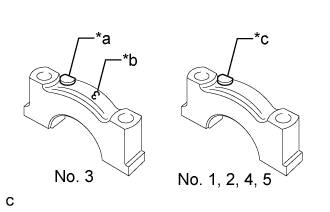 |
Check the front marks and numbers and install the crankshaft bearing caps onto the cylinder block.
| *a | Front Mark |
| *b | Number |
| *c | Front Mark and Number |
Apply a light coat of engine oil to the lower crankshaft bearings and threads of the crankshaft bearing cap bolts.
Step 1:
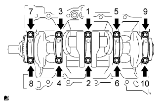 |
Using a 12 mm socket wrench, install and uniformly tighten the 10 crankshaft bearing cap bolts in several steps in the sequence shown in the illustration.
Step 2:
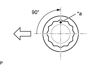 |
Mark each crankshaft bearing cap bolt head with a paint mark as shown in the illustration.
| *a | Paint Mark |
 | Engine Front |
Tighten the crankshaft bearing cap bolts 90° in the sequence shown in step 1.
Check that the paint marks are now at a 90° angle to the front.
Check that the crankshaft turns smoothly.
| 6. INSTALL PISTON SUB-ASSEMBLY WITH PISTON PIN |
Gradually heat the connecting rod up to 80 to 90°C (176 to 194°F).
Apply engine oil to the piston pin and the inside surface of the connecting rod sub-assembly.
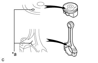 |
Align the front marks of the piston sub-assembly and connecting rod sub-assembly.
| *a | Front Mark |
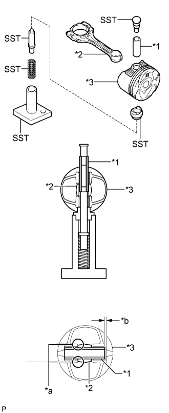 |
Using SST, push in the piston pin.
| *1 | Piston Pin |
| *2 | Connecting Rod Sub-assembly |
| *3 | Piston Sub-assembly |
| *a | Press |
| *b | 1.25 to 2.25 mm (0.0492 to 0.0886 in.) |
Check the fitting condition between the piston sub-assembly and piston pin by trying to move the piston back and forth on the piston pin.
| 7. INSTALL CONNECTING ROD BEARING |
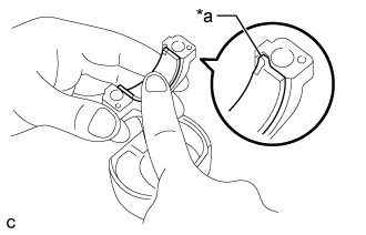 |
Align the connecting rod bearing claw with the grooves of the connecting rod and connecting rod cap.
| *a | Claw |
| 8. INSTALL PISTON RING SET |
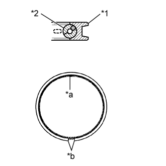 |
Install the oil ring expander and oil ring by hand.
| *1 | Oil Ring |
| *2 | Oil Ring Expander |
| *a | Oil Ring Expander Joint |
| *b | Oil Ring Ends |
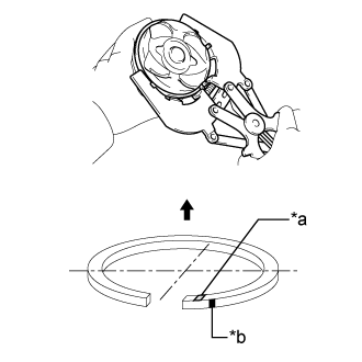 |
Using a piston ring expander, install the No. 2 compression ring as shown in the illustration.
| *a | Code Mark |
| *b | Paint Mark |
 | Up |
| Part | Paint Mark | Code Mark |
| No. 2 compression ring | Blue | 2R |
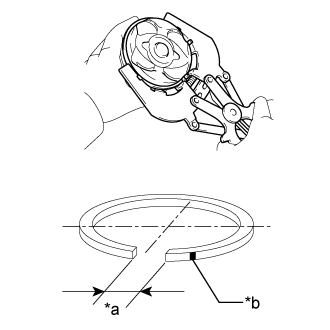 |
Using a piston ring expander, install the No. 1 compression ring as shown in the illustration.
| *a | Compression Ring Ends |
| *b | Paint Mark |
| Part | Paint Mark | Code Mark |
| No. 1 compression ring | Red | - |
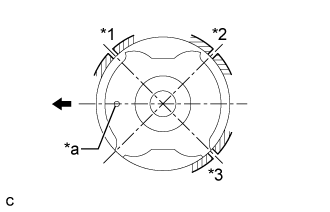 |
Position the piston rings so that the ring ends are as shown in the illustration.
| *1 | No. 1 Compression Ring |
| *2 | Oil Ring |
| *3 | No. 2 Compression Ring |
| *a | Front Mark |
| Engine Front |
| 9. INSTALL PISTON SUB-ASSEMBLY WITH CONNECTING ROD |
Apply engine oil to the cylinder walls, pistons, and surfaces of the connecting rod bearings.
Check the position of the piston ring ends.
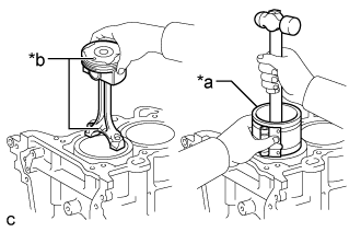 |
Using a piston ring compressor, push the correct piston sub-assembly and connecting rod subassembly into each cylinder with the front marks facing forward.
| *a | Piston Ring Compressor |
| *b | Front Mark |
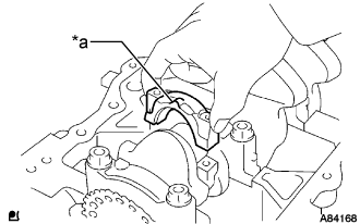 |
Check that the front mark of the connecting rod cap is facing forward and install the connecting rod cap.
| *a | Front Mark |
Apply a light coat of engine oil to the threads of the connecting rod cap bolts.
Step 1:
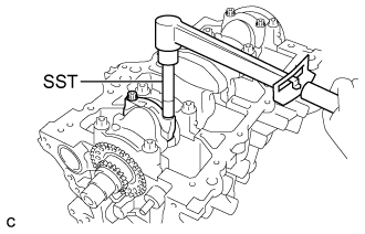 |
Using SST, install and alternately tighten the connecting rod cap bolts of the connecting rod cap in several steps.
Step 2:
|
Mark each connecting rod cap bolt head with a paint mark as shown in the illustration.
| *a | Paint Mark |
| Engine Front |
Tighten the connecting rod cap bolts 90° in the sequence shown in step 1.
Check that the paint marks are now at a 90° angle to the front.
Check that the crankshaft turns smoothly.